VD (E2.1) 10/2011 page 56/83
Set the positions “100” or “010” or “110” or “000” as follows:
Operation line 1 Operation line 2 Operation line 3
(no function)
1
0 0 Operation line 1 ON
0
1
0 Operation line 2 ON
1 1
0 Operation lines 1 and 2 ON
0 0 0 Operation line OFF
You can combine any of the switching states of the operation lines. You can recognize switching state
ON when the LED (7b) for operation line 1 and the LED (7c) for operation line 2 light up.
Operation lines 1 and 2 are designed for the following options:
• Operation line 1: Program controlled evacuation (option “vacuum module with pump”, see chap. 16.3)
•
Operation line 2: Program controlled venting (option “program controlled venting”, available via
BINDER INDIVIDUAL customized solutions)
You can connect any other device or electrical equipment with a nominal tension of 24 V DC and a
current consumption of max. 0.4 A.
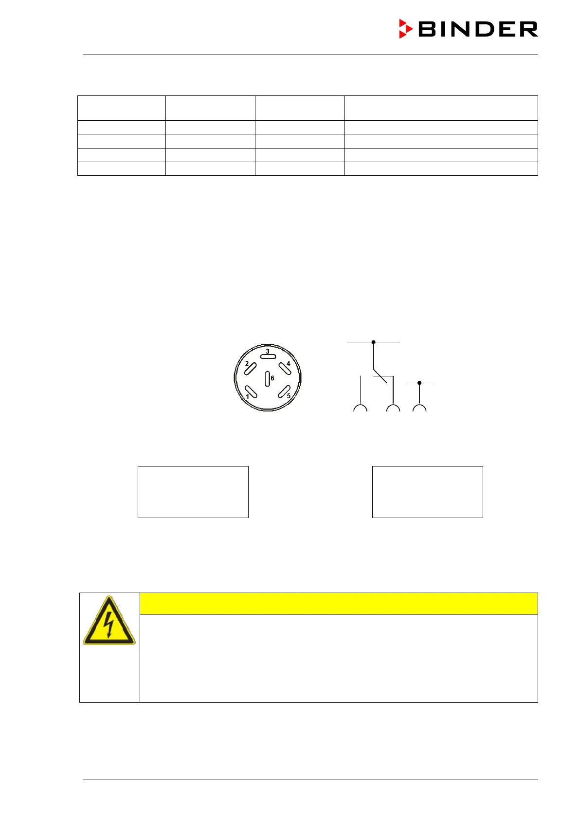
Establish the connection via the DIN sockets at the rear of the oven:
Figure 14: Pin configuration of the DIN sockets (15) and (16)
OPERATION LINE 2
OUTPUT
24V DC / MAX. 0,4A
OPERATION LINE 1
OUTPUT
24V DC / MAX. 0,4A
Figure 15: Legend at the DIN socket (15) Figure 16: Legend at the DIN socket (16)
A suitable DIN plug is enclosed.
Maximum loading capacity of the switching contacts: 0.4 Amp.
CAUTION
Overloading the switching contacts.
Damage to the switching contacts and connection sockets.
∅ DO NOT exceed the maximum switching load of 0.4 Amp.
∅ DO NOT connect any device with a higher load.
ONLY connect devices with a nominal tension of 24 V DC.
24 V DC +
24 V DC -
1 2 3