Operating instructions FK 23 Machine and operating elements
6.066.98.5.10.05 en 5 - 3
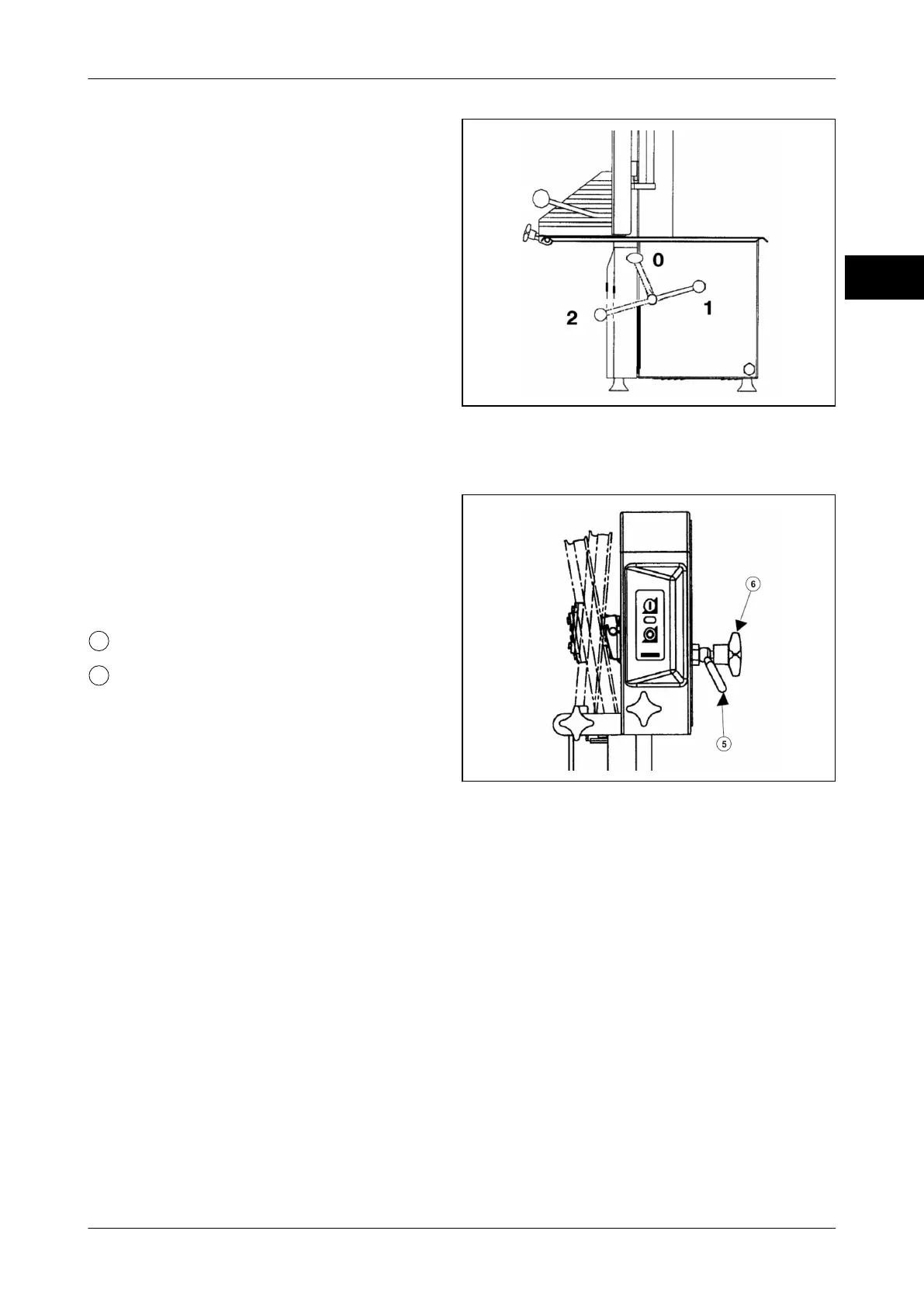
5
Position 0 = saw blade without tension:
Position for periods during which the ma-
chine is not in use / after work is completed
Position 1 = saw blade with tension: Po-
sition for sawing operation
Position 2 = saw blade released: Position
for saw blade replacement, saw blade de-
flector and drive disk deflector are disen-
gaged.
Fig. 10: Clamping unit
5.6 Adjustment device for upper wheel
The adjustment device consists of a locking
lever and a threaded spindle with star knob.
It serves to change he axial position of the
top wheel and consequently the running po-
sition of the saw blade.
Locking lever
Threaded spindle with star knob
Fig. 11: Adjustment device
5.6.1 Change saw blade running
The circular rotation of the blade is adjusted at the factory to an optimal positioning of the
blade and with regard to blade guide and upper wheel,
The back of the saw blade slightly touches the pin inside the guides at a distance of ap-
prox. 1 mm from the upper wheel band.