Operating instructions iS10 / iS20 Technical data
38019417000 en 105
13
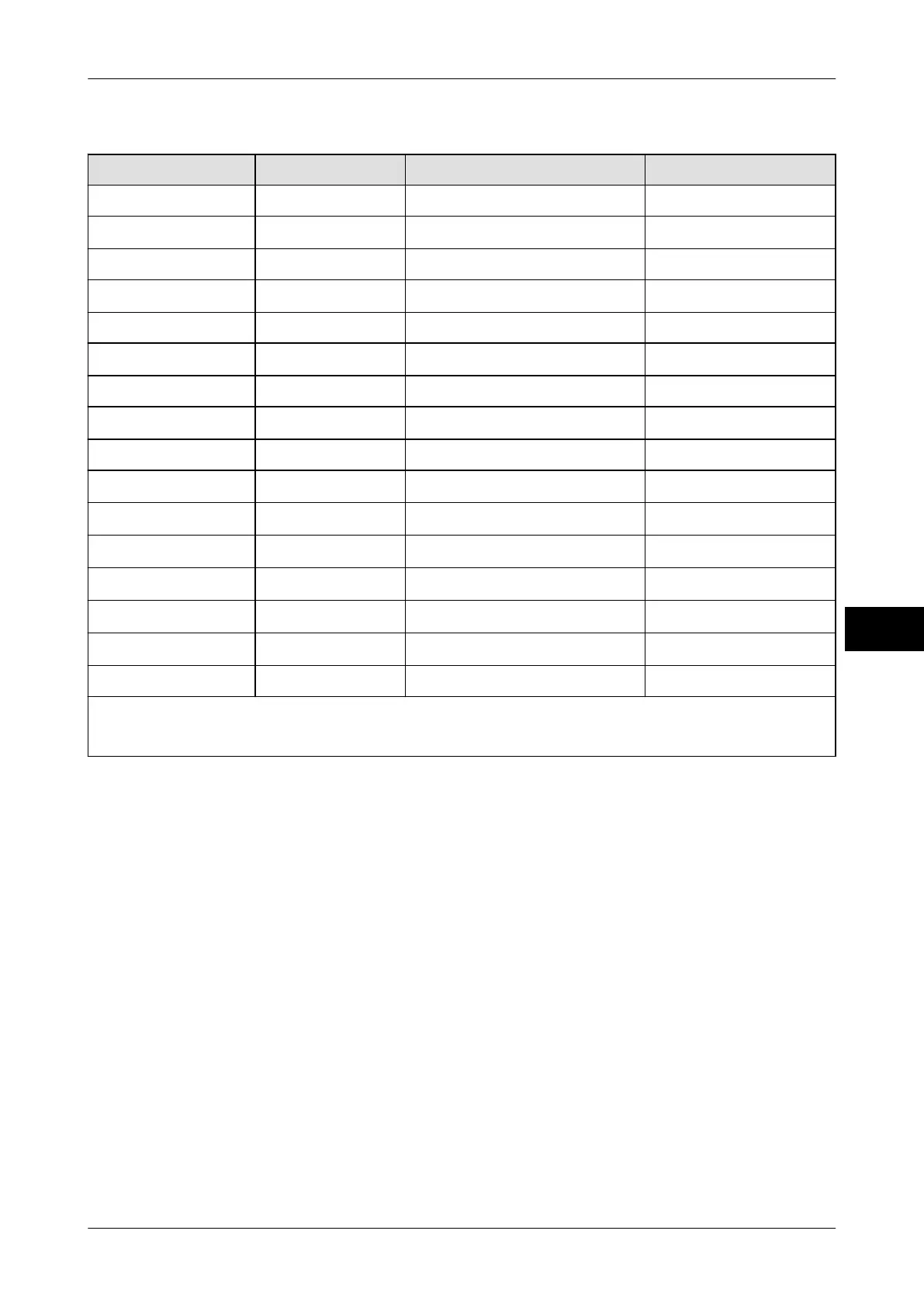
16-pin connection Name Function Wire color
1 GND white (WH)
2 Channel 1 input
NC
1)
brown (BN)
3 Channel 1 output lower tolerance limit green (GN)
4 Channel 2 input
NC
1)
yellow (YE)
5 Channel 2 output Target value gray (GY)
6 Channel 3 input
NC
1)
pink (PK)
7 Channel 3 output upper tolerance limit blue (BU)
8 Channel 4 input
NC
1)
red (RD)
9 Channel 4 output Scale in no-motion condition black (BK)
10 Channel 5 input
Taring
2)
purple (VT)
11 Channel 5 output
NC
1)
gray-pink (GY-PK)
12 Channel 6 input
Delete tare
2)
red-blue (RD-BU)
13 Channel 6 output
NC
1)
white-green (WH-GN)
14 Channel 7 input
Item recording, adding
2)
brown-green (BN-GN)
15 Channel 7 output
NC
1)
white-yellow (WH-YE)
16 GND brown-yellow (BN-YE)
NC
1)
= not connected
2)
= Unused inputs must be grounded.
13.8 Connections
The following connections are possible:
– 1 x load receptor
– 1 x PIO (4 outputs, 3 inputs)
– 2 x serial interfaces
– 1 x Ethernet (100 MBit/s IPv4)