Operating instructions iS10 / iS20 PC/EDP and printer interface
38019417000 en 51
6
Logic acknowledgments can be selected or deselected in the EDP pa-
rameter menu (step 74).
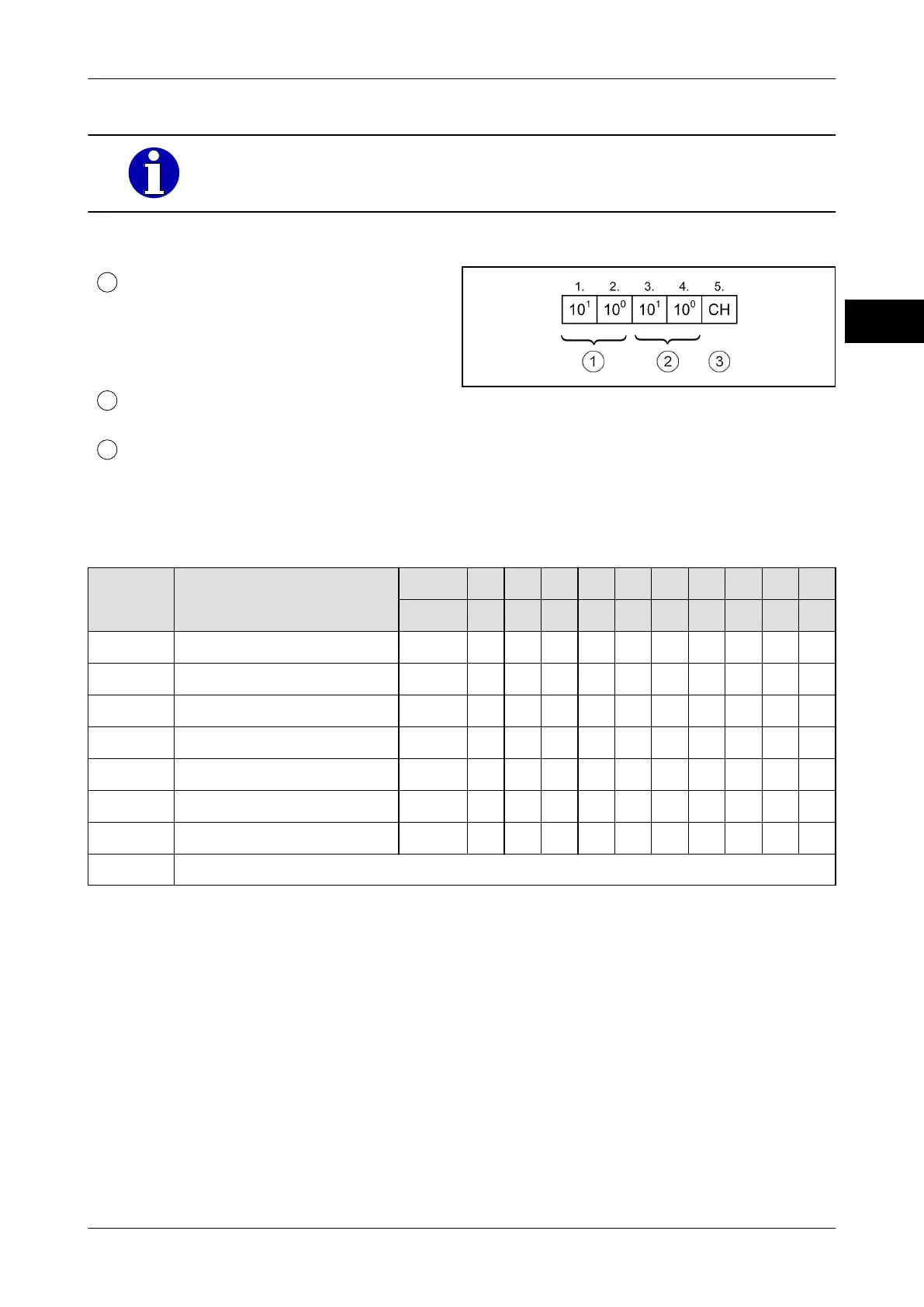
Data set header
Record no.
02 = Item recording, adding +
03 = Total*
07 = Item recording, non-adding
08 = Independent of recording
System no.
Parameter menu step 75
Scale no.
1 = Scale 1
Fig. 16: Data record head 5 byte
Data output formats: Weight values
The data bits of the status character provide information about the status of the scale.
Data bit
Functions Hex 20 21 22 23 24 25 28 29 2A 2B
ASCII SP ! " # $ % ( ) * +
D0 = 1
In equilibrium X X X X X
D1 = 1
In underload X X X X
D2 = 1
In overload X X
D3 = 1
In the zero point range X X X X
D4 = 0
Fixed
D5 = 1
Fixed X X X X X X X X X X
D6 = 0
Fixed
D7 Parity bit
If the scale gross is under zero and is still within zero setting range, the data bits are D1=1
(underload) and D3=1 (zero setting range). Scale can be set to zero.
Depending on decimal point and number of display digits the characters before the highest
ranking decade are sent with space SP.
If the dimension consists of a character, a space SP is set on the last digit. The position of
the decimal point in the data group depends on the connected scale according to the serv-
ice menu setting.
The minimum transmission rate for continuous sending of data is 9600 bit/s.