32
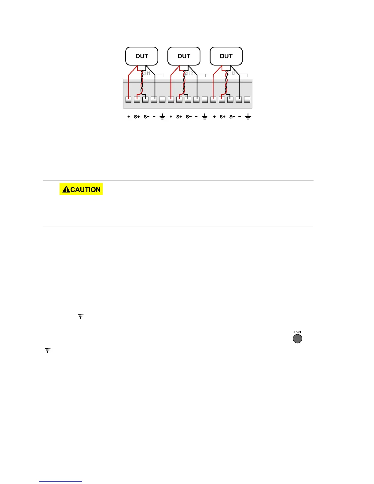
Figure 17 - Remote sense connections
2. Connect the S+ to the Device Under Test (DUT)’s positive (+) terminal, and connect the S-
to the DUT’s negative (-) terminal.
3. Double check that the connections matches to Figure 20.
4. Power ON the supply and then configure and enable the output.
DO NOT at any time disconnect the wires from the S+ and S- terminals to the DUT
while output is enabled (ON). Doing so may damage the power supply and cause
5 Remote Operation
The power supply comes standard with RS232, USB, and GPIB remote interfaces. Users can
program the power supply by using SCPI (Standard Commands for Programmable Instruments)
commands over any one of the remote interfaces. This section will describe how to set up all of
the supported interfaces.
Note: The indicator will appear on display when the power supply is successfully connected
to a PC remotely through any remote interface. Keys on the front panel will be locked until the
instrument is in LOCAL mode. To return to LOCAL mode from the front panel, press . The
indicator will disappear when the instrument is in LOCAL mode.
5.1 Interface Configuration
RS-232
For RS-232 connectivity, refer to the diagram below for pin out information. The RS-232 is
labeled in the rear panel and it is a female DB-9 interface.
www.GlobalTestSupply.com
Quality BK Precision Products Online at: sales@GlobalTestSupply.com