15
EN
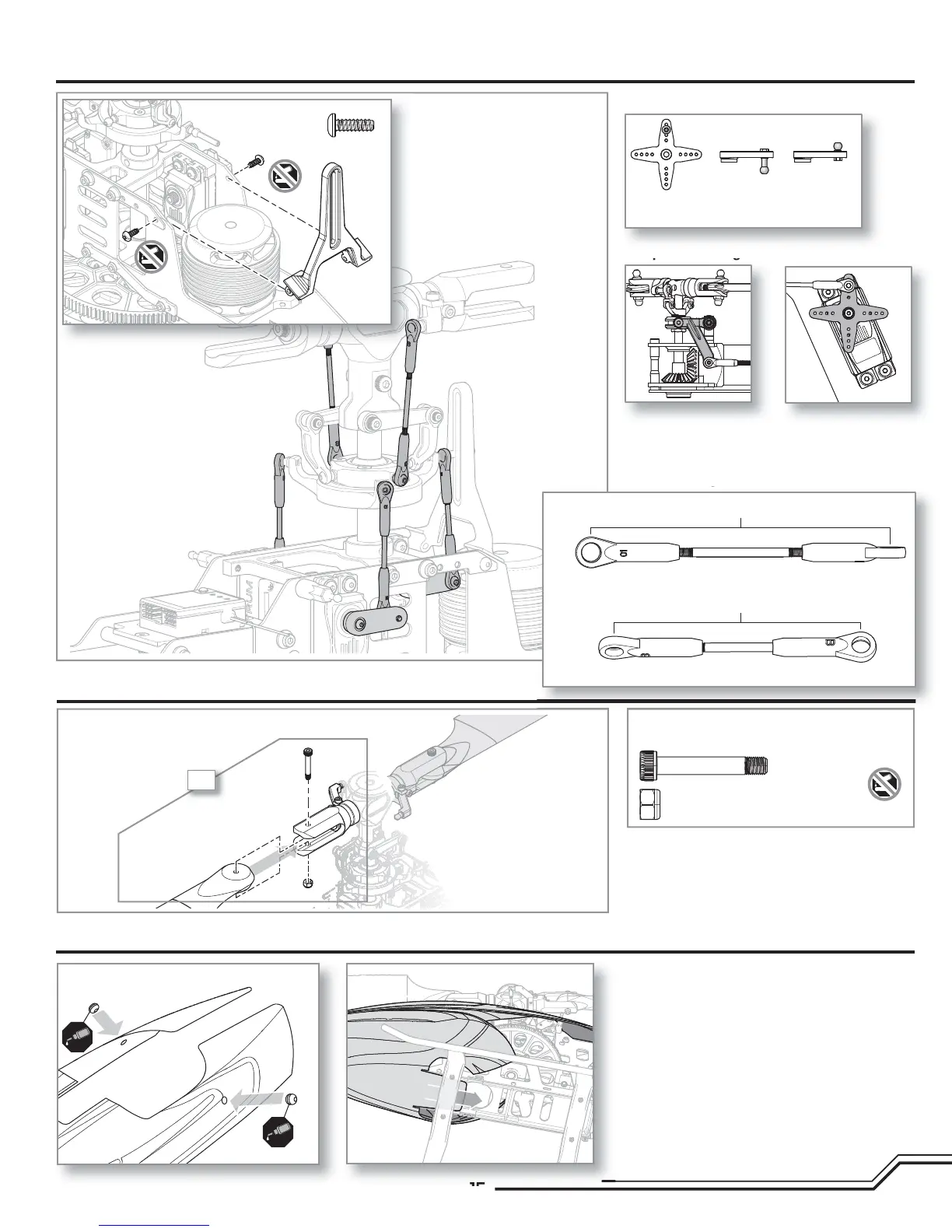
Servo ball link placement
Tail pushrod alignment
Tail servo Rear swash
servos (x2)
Front swash
servo
Canopy Installation
Main Rotor Installation
Servo Arms and Links Installation
• The rotor blades should be tight enough to hold their
position if you hold the helicopter sideways, but loose
enough to swing freely if you move the helicopter
and stop abruptly.
Main Rotor Blade parts
2X
Main Rotor Blades
Main blade shoulder bolt M4 X 30 (x2)
M4 Lock nut (x2)
Canopy Grommets
Tail pitch bellcrank
neutral position
(viewed from the bottom)
Tail servo arm
neutral position
(viewed from the right side)
A
A
Pushrod lengths
Swash to blade grip link, 68mm (x2)
68mm
Servo to swash link, 56mm (x3)
56mm
A
B
B
B
B
Self tapping screw
M3 X 8 (x2)