7
EN
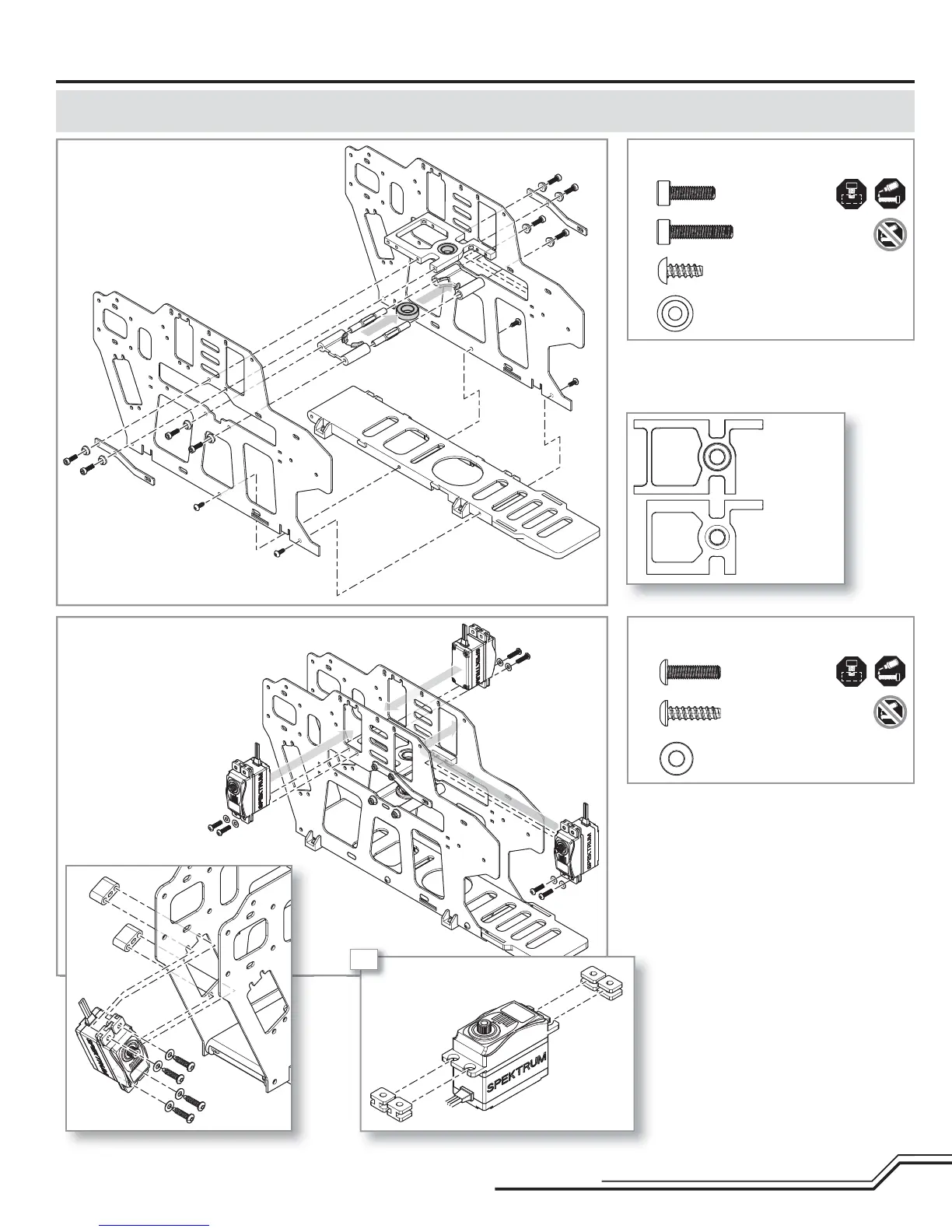
• At this stage of the assembly, do not tighten
the bearing blocks or bottom plate screws.
Frame Assembly (F)
Step F1 parts (bags F1, F2, and F3)
Step F2 parts (bag F5)
Step F1
Step F2
ASSEMBLY NOTE: Before assembly, plan your wire routing for the servos. At any point where the servo wire is going to pass through or cross the frame plates,
use sandpaper to round the edge of the frame plate to prevent the wire from chafi ng.
Cap head bolt
M3 X 10 (x4)
Cap head bolt
M3 X 14 (x4)
Self tapping screw
M3 X 8 (x4)
M3 recessed washer (x8)
Button head screw
M3 X 12 (x6)
Self tapping screw
M3 X 12 (x4)
Servo washers (x10)
A
A
A
A
A
B
C
B
A
A
B
B
C
C
C
C
B
B
Top block
Middle block
4X