6
EN
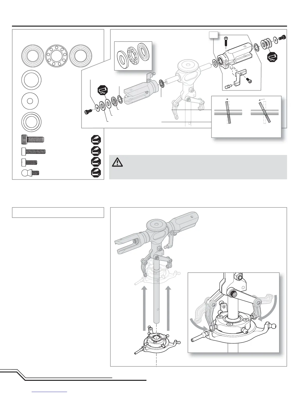
• Loosely install bolts B and C before tightening.
• The stepped washer faces the radial bearing in the
blade grip.
Head Assembly cont’d
2X
Step H4
Step H5
Step H4 parts (bag H3)
Step H5 parts (bag H4)
Smaller I.D. thrust washer race
Larger I.D. thrust washer race
Bearing cage
Spindle bolt washer
Thrust washer
Step washer
Thrust bearing (x2)
Thrust washer
10 X 14 X .8 (x2)
Spindle bolt washer
4 X 12 X 1 (x2)
Step washer (x2)
M4 X 12 bolt (x2)
M3 X 14 bolt (x2)
M3 X 8 bolt (x2)
Control ball (x2)
A
B
A
A
B
C
C
Larger inner
diameter (I.D.)
Smaller inner
diameter (I.D.)
WARNING: Any time you loosen the spindle bolts, completely clean the bolts with denatured
alcohol making sure you have removed any residual oil. When putting bolts back on, apply
medium-strength threadlock to the bolts and allow time for the threadlock (about 4 to 6 hours) to dry
before attempting to fl y your helicopter.