12
BOC Smootharc Multi 180/200 Operating manual
Installation
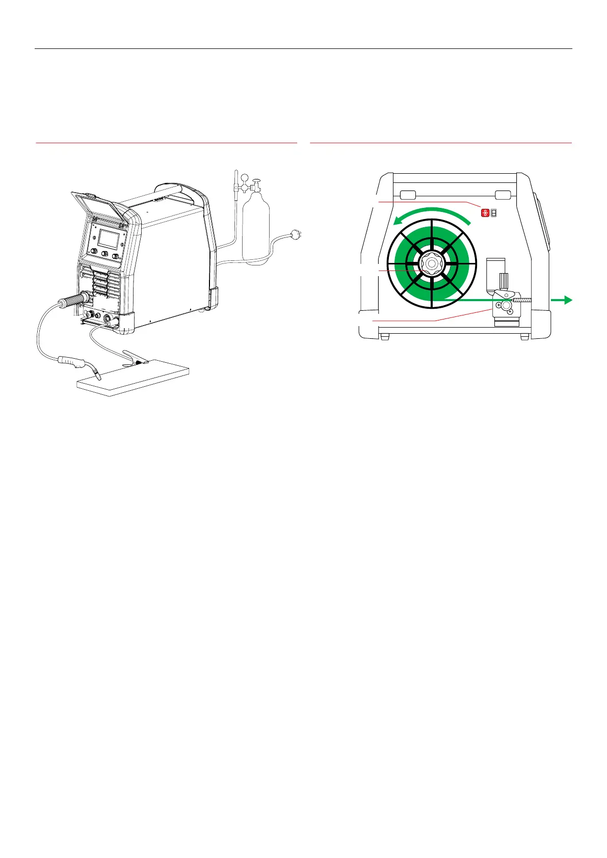
Installation for MIG/MAG process Wire feed installation
MIG/MAG
1. Connect the gas hose to the regulator and the rear of the machine.
Select correct shielding gas for the application.
2. Insert the [E] work return lead connector into [14] negative terminal
in the front panel.
3. Select correct welding wire for application (see page 38). Ensure you
are wearing safety glasses before loading wire into your machine. Fit
the wire spool to the machine.
4. Select the appropriate feed roller to suit the wire being used. This
machine comes complete with three types of wire feed rollers:
- V groove for use with solid carbon manganese and stainless steels;
- Knurled for use with FCAW wires;
- U groove for aluminium.
5. Install the wire: loosen the knurled nut from the spool holder; x
the welding wire reel onto the spool holder [3] so that the brake pin
locks into the spool bore; fasten the wire spool using the spool nut.
Ensure the welding wire reel is installed as per diagram above right,
feeding anti-clockwise.
6. Loosen the wire feed tension knob and insert the wire. Tension rollers
ensuring the wire is gripped suciently so as not to slip but avoid
over tightening as this can aect feed quality and cause wire feed
components to wear rapidly. Wire inching is achieved by pressing and
holding the torch trigger.
13
12
1411
A
10
E
3 Wire feed unit
2 Wire spool holder
1 Wire inch button
7. Fit and tighten the [A] torch on the [10] output connection. Ensure
correct torch liner and contact tip are selected.
8. Select the correct polarity for the type of wire used as indicated on
the consumable packaging. For most solid wires the terminal should
be set as torch positive. Therefore the [E] work return lead should be
connected to the [14] negative terminal.