38
BOC Smootharc Multi 180/200 Operating manual
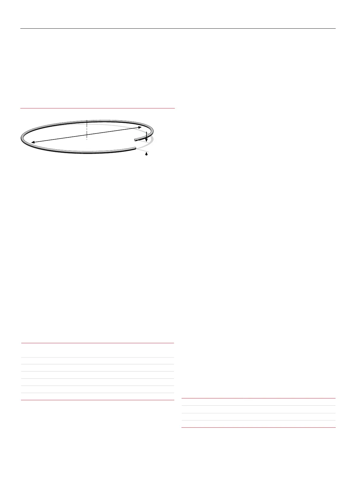
Cast
Helix
Cast – Diameter of the circle
Helix – Vertical height
Cast and Helix
Consumables
Chemical composition
As a general rule the selection of a wire is straightforward, in that it
is only a matter of selecting an electrode of similar composition to
the parent material. It will be found, however, that there are certain
applications that electrodes will be selected on the basis of its
mechanical properties or level of residual hydrogen in the weldmetal.
Solid MIG/MAG wires are all considered to be of the 'low Hydrogen type'
consumables.
The following table gives a general overview of the selection of some of
the BOC range of MIG/MAG wires for the most common materials.
Common materials welded with BOC MIG wire
AS2074 C1,C2,C3,C4-1,C4-2,C5,C6 BOC Mild Steel MIG Wire
AS/NZS1163 C250 BOC Mild Steel MIG Wire
AS/NZS3678 200,250,300 BOC Mild Steel MIG Wire
ASTM A36,A106 BOC Mild Steel MIG Wire
Stainless Steel Grade 304/L BOC Stainless Steel 308LSi
Stainless Steel Grade 309 BOC Stainless Steel 309LSi
Stainless Steel Grade 316/L BOC Stainless Steel 316LSi
Surface condition
The welding wire must be free from any surface contamination including
mechanical damage such as scratch marks.
A simple test for checking the surface condition is to run the wire
through a cloth that has been dampened with acetone for 20 secs.
If a black residue is found on the cloth the surface of the wire is not
properlycleaned.
Cast and helix
The cast and helix of the wire has a major inuence on the feedability of
MIG/MAG wire.
If the cast is too large the wire will move in an upward direction from the
tip when welding and if too small the wire will dip down from the tip.
The result of this is excessive tip wear and increased wear in the liners.
If the helix is too large the wire will leave the tip with a corkscrew eect.
Power sources
Power sources for MIG/MAG welding is selected on a number of dierent
criteria, including:
→ Maximum output of the machine
→ Duty cycle
→ Output control (voltage selection, wire feed speed control)
→ Portability
The following table gives an indication of the operating amperage for
dierent size wires.
Wire size Amperage range (A)
0.8 mm
60–180
0.9 mm 70–250
1.0 mm 90–280
1.2 mm 120–340