10
4.2 Electrical connections
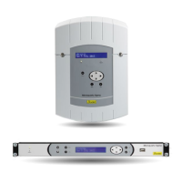
4.2.1 Wall mounted version
1/ Connect the cables to the corresponding terminal strips as shown in the gure below.
Meaning of status of LEDs on a RJ45 connector :
- The green LED reects network activity.
The yellow LED indicates the speed of the network:
off=10 Mbps on=100 Mbps.
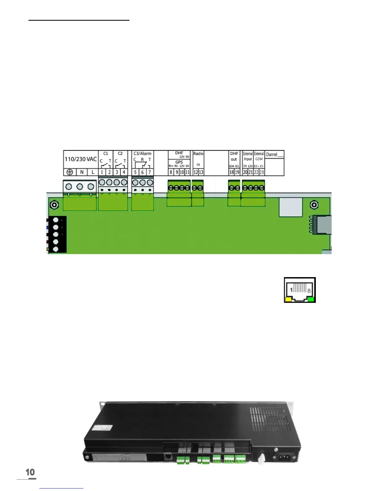
4.2.2 Rack 19’’ version
The connectors are directly accessible at the rear of the Rack unit.
110-
230VAC
GPS input
DCF
radio input
External input
See the limit
characteristics of
these circuits on
page 40
Circuit C1
Circuit C2
Circuit C3
DHF output
Output communication
IP connection
RJ45 connector
Attach the wires to each other, near
the terminal strips.