EM-RES-03 10/0738
For the system bus, the input data of the TxPDO’s are also displayed as input pa-
rameters and the output data of the RxPDO’s as sources.
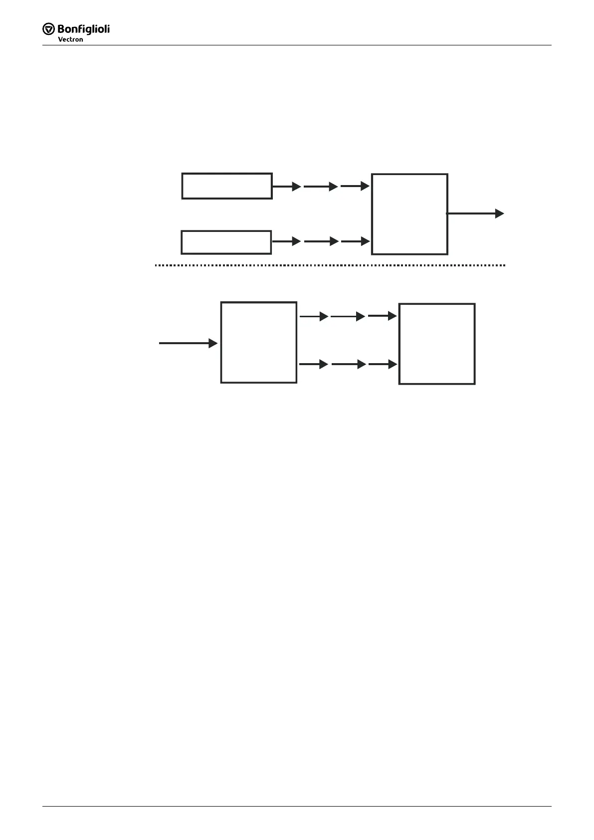
Example 2:
Function A
Inverter 1
Function B
Inverter 1
Source-No. 27
Source-No. 5
TxPDO
Inverter 1
Parameter 977
Parameter 972
system bus
RxPDO
Inverter 2
Source-No. 727
Source-No. 724
Function C
Inverter 2
Parameter 125
Parameter 187
system bus
Example 2 displays the same situation as Example 1. But now, the functions A and B
are in frequency inverter 1 and function C in frequency inverter 2. The connection is
done via a TxPDO in frequency inverter 1 and a RxPDO in frequency inverter 2. Thus,
the parameterization for this connection is:
Frequency inverter 1
Parameter 977 = Source-No. 27
Parameter 972 = Source-No. 5
Frequency inverter 2
Parameter 125 = Source-No. 727
Parameter 187 = Source-No. 724
As the links with the system used exceed the device limits, they are termed "virtual
links".

 Loading...