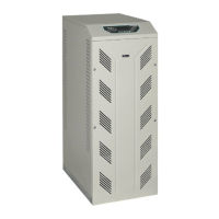
Front panel
Rev.B JSE410920 22/07/08 JUD408312
3 of 29
1. INTRODUCTION
The front panel of the UPS, consisting of a four-row alphanumeric display plus 5
function keys, allows the complete monitoring of the UPS status.
The mimic flow helps to understand the operating status of the UPS.
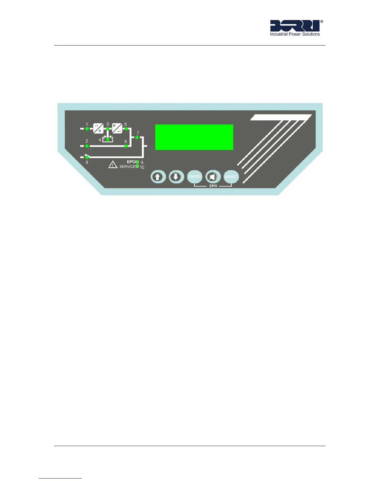
Picture 1 - Front panel B8031 and B8033
2. DESCRIPTION
2.1 MIMIC DESCRIPTION
Picture1 shows the mimic present on the display, with the names of the circuit
breakers/isolator switches of the UPS. Also the led's and blocks that comprise the UPS
are clearly identified.
LED 1 ⇒ Lit-up green = Mains present at the rectifier input.
Green flashing = Wrong input phase sequence.
Off = Rectifier input mains fault.
LED 2 ⇒ Lit-up green = Emergency line present and in order.
Green flashing = Wrong bypass phase sequence.
Off = Emergency line (bypass) fault.
LED 3 ⇒ Lit-up green = Rectifier feeding correctly.
Green flashing = Rectifier in alarm.
Lit-up red = Inverter input voltage out of tolerance.
LED 4 ⇒ Lit-up green = Battery OK.
Green flashing = Battery discharging or battery in test.
Orange flashing = BCB open.
Lit-up red = Battery test aborted.
LED 5 ⇒ Lit-up green = Inverter static switch closed.
Otherwise off.