Electrical Connections
5–7
1070 073 822-104 (02.06) GB
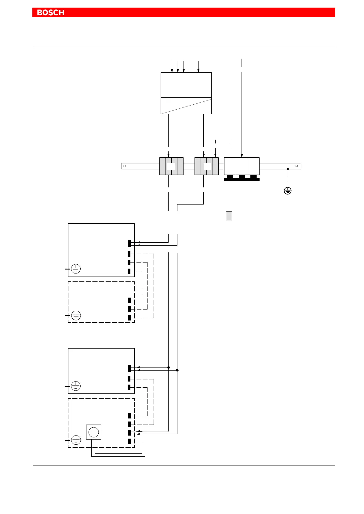
Cross-sections
dependent on current
draw, but MIN 4
mm
2
.
At greater current
draw, use 2 x 4 mm
2
Power supply with
safety transformer,
as per EN 60742
24 VDC
(1) Easily removable and visible.
(2) Preferred installation of PE terminal bars, i.e., electrically
conductive on the mounting plate. Both ends of PE terminal bars
must be connected to mounting plate by means of copper straps
of a length not exceeding 200 mm.
At minimum, the cross-section of the copper straps must be
equal to that of the supply cable.
(3) 0.5 mm
2
, up to 4 m
0.75 mm
2
, up to 6 m
1.5 mm
2
, up to 10 m
Distances in excess of 10 m necessitate
a separate power supply at the machine!
: Terminals in isolated arrangement
A
10
2
(green/yellow)
(2)
A B
A
= Terminal block 4
2
B = Terminal block 10
2
Max. length 4 m
6
2
(1)
(blue)
0 V Load24 V Load
Earth bar
Cross-sections
dependent on current
draw, but MIN 0.5
mm
2
(3)
PE
PE
L1
L2
L3
10
2
(green/yellow)
BF2xxT
Control Panel
X33
LVDS
X34
PE
PE
IPC
(24 VDC version)
X10_1
Power supply
X11
LVDS
COM2
BF3xxT
Control Panel
X33
LCD
X10_1
PE
PE
IPC300
(24 VDC version)
X10_1
Power supply
X11
LCD
X10_2
Fan power
Fan