Do you have a question about the Bosch Rexroth IPC and is the answer not in the manual?
Manual provides information for proper product use, covering functional options and scenarios.
Manual is designed for trained personnel requiring specific knowledge of configuration and startup.
Identifies danger symbols: High voltage, Corrosive battery acid, ESD, and disconnection requirements.
Explains symbols for DANGEROUS ELECTRICAL VOLTAGE, DANGER, CAUTION, and special interest items.
Addresses hazards from ineffective Emergency-STOP devices and unauthorized product modifications.
Details protective measures for electrostatically sensitive devices (ESDs) like training and handling.
Lists available documentation, part numbers, drive letter conventions, and software trademarks.
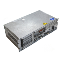
Describes the two equipment versions: 230/115 VAC and 24 VDC, detailing their power supply compatibility.
Provides detailed specifications for IPC and IPC300, covering processor, memory, storage, interfaces, and dimensions.
Details the availability of PCI and ISA bus expansion slots, with a caution for non-approved cards.
Specifies storage and ambient temperatures, humidity, atmosphere, protection categories, and vibration resistance.
Lists the various standards and directives that the IPC/IPC300 system components comply with.
Monitors internal housing temperature, triggering warnings at 50°C and shutdown at 65°C.
Explains UPS activation during power failures or high temperatures for safe shutdown.
Details how the system handles voltage drops between 800 ms and 60 seconds for safe shutdown.
Describes the UPS program's role in controlling UPS, battery pack, and temperature monitoring.
Instructions for starting, stopping, hiding, exiting, and using the simple operating menu for UPSplus.
Details the configuration dialog for UPSNT, covering COM Port, Shutdown Parameter, and Advanced Controls.
Explains options like Enable Accu Test for battery testing and Enable Temp Control for temperature monitoring.
Covers operation requiring Administrator privileges and managing the UPSNT service.
Details configuring the UPSNT program for IPC300 via the control panel and NT service.
Explains enabling battery tests on restart and handling of errors and temperature warnings.
Warns about hazardous conditions from pollutants and the need for filter servicing.
Provides guidelines for installed positions, clearances, and ventilation requirements for IPC/IPC300.
Presents detailed drawings showing the physical dimensions and connector layouts for the IPC.
Instructions for installing the IPC/IPC300 into a 19-inch mounting frame.
Emphasizes that connections must be made only while the system is switched off.
Details critical requirements for protective earth conductors and screening for system integrity.
Covers measures to suppress interference and EMC issues for operational safety.
Explains the 24 VDC power connection, including terminal assignment and fuse requirements.
Provides wiring diagrams showing power connections for IPC and IPC300 24VDC versions.
Details the 230/115 VAC power connection, Overvoltage Category II, and transformer use.
Illustrates the 230 VAC mains connection via a separation transformer.
Presents wiring diagrams for 230/115 VAC power connections for IPC and IPC300.
Lists installed IPC connector types, their physical connectors, and mating connectors.
Shows the layout of connectors on IPC and IPC300 front panels, including DIP switches.
Details serial ports, including pin assignments for COM1 and general information.
Describes COM2's assignment for touch screen or RS-422/485 service.
Explains the X57 port as RS-485/422 and its configuration via S3 DIP switch.
Details the COM3 serial port, which is freely assignable.
Describes the COM4 serial port, assigned to UPS logic.
Notes that the USB interface is currently not supported for USB functions.
Information on setting communication parameters for COM ports via Control Panel and BIOS.
Details the LPT1 parallel port for printers/scanners, including modes SPP, EPP, and ECP.
Describes the Ethernet connection for network communication and its driver configuration.
Covers LVDS video transmission for BF2xxT panels, designed for longer, interference-free routes.
Explains how to select display resolutions for IPC using the S3 DIP switch.
Details the Gigabit interface for BF3xxT panels, handling video and touch screen controller signals.
Guide to selecting display resolutions for BF3xxT panels using the S1 DIP switch.
Describes the VGA port for external monitors, allowing parallel operation with the operator panel.
Explains VGA modes, resolutions, and how to bypass settings using DIP switches.
Details the X11 connection for power, backlight, and mouse/keyboard signals to the control panel.
Describes the PS/2 mini DIN keyboard connector and necessary adapter information.
Details the PS/2 mouse port and relevant BIOS settings for mouse support.
Explains the functions of the five LEDs and the RESET pushbutton on the unit's backside.
Outlines tasks for yearly maintenance: checking connections, fans, filters, batteries, and data backup.
Details the replaceable power supply fuses for 24 VDC and 230 VAC, and their accessibility.
Provides a step-by-step procedure for replacing the hard disk, including BIOS configuration.
Details the procedure for safely removing and replacing the CD-ROM drive.
Outlines the procedure for replacing the 3.5" floppy disk drive.
Covers conditions for battery replacement and the relationship between charging cycles and ambient temperature.
Describes how to install expansion cards, including precautions for combination slots.
Details PCI and ISA slot IRQ and DMA settings within the IPC's BIOS.
Details PCI and ISA slot IRQ and UMB settings within the IPC300's BIOS.
Lists the licensed BIOS software versions for the IPC and IPC300.
Specifies the operating systems and UPS utility programs available for IPC and IPC300.
Describes the Bosch PCL software PLC, its components, and interconnection capabilities.
Explains the use of Typ3 osa software with control panels as an operating terminal via Ethernet.
Details MADAP Studio's function as a visual display terminal for automatic system diagnostics.
Reference to the price list for order numbers of basic units, operating systems, and components.
Lists available accessories, such as connecting cables, with their respective order numbers.
Provides a list of spare parts like fuses, battery packs, drives, and RAM modules with order numbers.
A glossary of abbreviations used throughout the manual.
An alphabetical index of topics covered in the manual for easy reference.
| Brand | Bosch Rexroth |
|---|---|
| Model | IPC |
| Category | Industrial PC |
| Language | English |