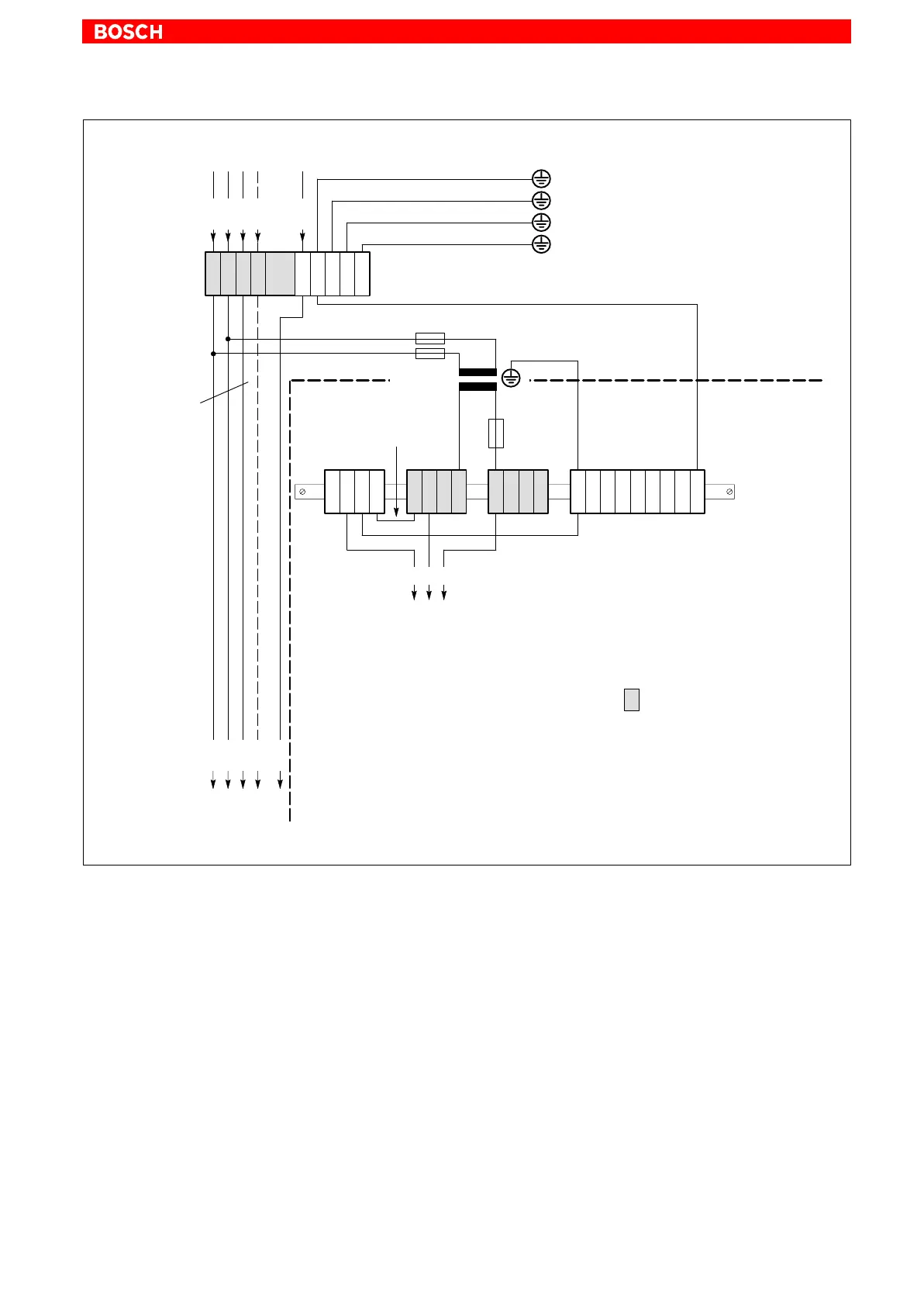
Electrical Connections
5–9
1070 073 822-104 (02.06) GB
4
2
(green/yellow)
L1
L2
L3
N
PE
U1
V1
W1
N
PEPE N1
16
2
(green/yellow)
min.16
2
(green/yellow)
to control cabinet housing
400 V
230 V
4
2
(green/yellow)
PE
N1
U2
4
2
(green/yellow)
16
2
(green/yellow)
to machine
6
2
(green/yellow)
all housing components (PE lug)
To utilize neutral
conductor ”N”,
operator
permission is
required!
PE
10
2
(green/yellow)
PE terminal bar for = V wiring
(see Fig. 2)
= Terminals in
isolated arrangement
PE
PE
PE
PE
PE
Fuses; motor protection switch preferred
L1.1
L2.1
L3.1
N
230 V supply
IPC (see Fig. 3)
possibly. 230 V fan
Service sockets
U2
e.g., drives
Incoming mains
PE star-point connection
Transform
er, as per
EN 60742
230 VAC power connection via separation transformer