Access Modular Controller 2 Introduction | en 11
Bosch Security Systems B.V.
Installation manual
2021-04 | V04 | IM
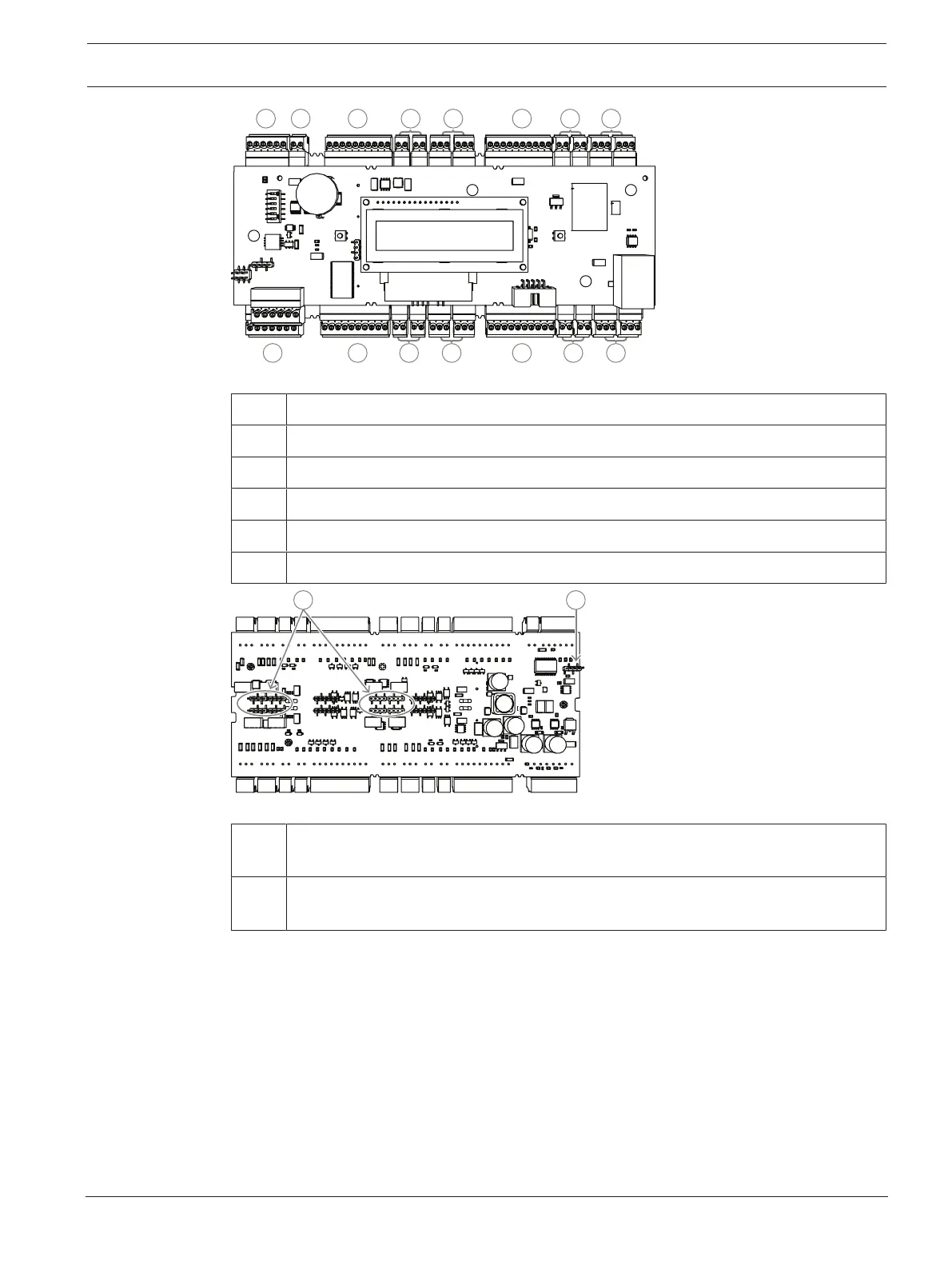
12 13
14 15 1516 17 16 17
15 16 17 15 16 17
Figure3.4: Interfaces - overview
12 RS-485 extension module bus
13 External tamper contact
14 Connector for power supply
15 Wiegand interfaces for card readers
16 Connectors for analog inputs
17 Connectors for relay outputs
Figure3.5: Jumber (back)
18 Jumper for setting either voltage free relay output (“dry” mode) or looped-in voltage
from the AMC internal power supply (“wet” mode).
19 Jumper: Equalization of potential between different systems and earth ground
(shield) for the extension interface.