30 en | Installing Access Modular Controller 2
2021-04 | V04 | IM
Installation manual
Bosch Security Systems B.V.
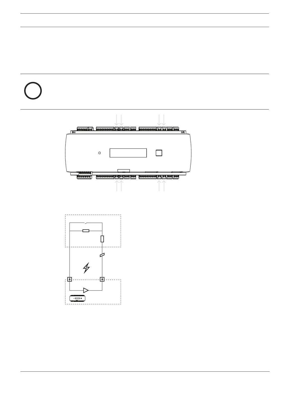
4.13 Connecting analog input devices
The AMC2 has eight analog inputs, for example, for potential-free lock mechanisms, or to
detect whether a lock is closed or open. The inputs will be connected to the 2-pin pluggable
screw connectors: S3, S4, S8, S9, S15, S16, S20 and S21 - refer to
Connecting diagrams, page
46
.
Notice!
Risk of damage to equipment
Do not connect external power supply to the AMC2 inputs.
When connecting a relay output to an AMC2 input use dry mode with potential-free contact -
refer to
Connecting relay outputs, page 28
.
Figure4.21: Location of the analog input connectors
The AMC2 can also detect the wiring conditions ‘short circuit’ and ‘broken’, and hence trigger
an alarm if the appropriate devices are connected.
door open/closed
broken wire
short circuit
ParallelR
AMC-4
Analog Input
SerialR
1. Door open: R
S
+ R
P
2. Door closed: R
S
3. Open wire: R
S
+ R
P
= ∞
4. Short circuit: R
S
+ R
P
= 0
The resistor values can vary and depend on the used lock system.
The extension package includes 2,2 kΩ resistors which can be used to replace R
S
and R
P
resistor.