28 en | Installing Access Modular Controller 2
2021-04 | V04 | IM
Installation manual
Bosch Security Systems B.V.
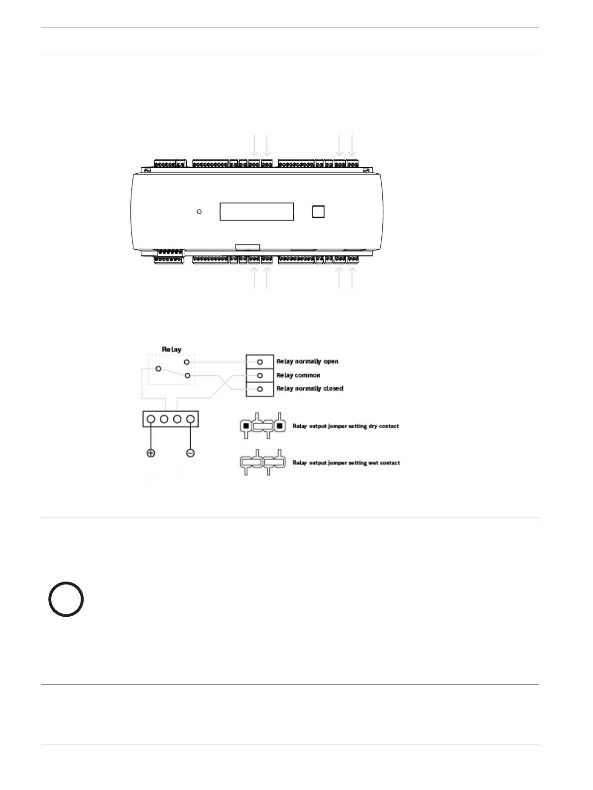
4.12 Connecting relay outputs
To operate locks or alarm systems, the AMC2 has eight relay outputs. The outputs will be
connected to the 3-pin pluggable screw connectors S5, S6, S10, S11, S17, S18, S22 and S23 -
refer to chapter
Connecting diagrams, page 46
.
Figure4.17: Location of the relay output connectors
Each relay output can operate in ‘wet’ mode, using the AMC2 internal 12/24 Vdc power supply
for external devices or ‘dry’ mode with potential free contacts for externally powered systems.
Figure4.18: Wet mode and dry mode of the AMC2 relay outputs
Notice!
Risk of damage to equipment
To prevent damage to the relays, note these specifications:
- The maximum switching current is 1.25 A.
- The maximum switching voltage is 30 VDC.
- Only OHM resistive load can be connected to the relay.
- Inductive loads have to be short circuited using recovery diodes. The diodes (1N4004) are
supplied with every AMC2.
- If you need higher voltage or current for special applications, or electric door holding
magnets, you have to use coupling relays (e.g. Wieland flare move) on the outputs.
- Note that the coupling relays must be selected according to the supply voltage (12 V, 24 V)
of the AMC2.