Access Modular Controller 2 Installing | en 29
Bosch Security Systems B.V.
Installation manual
2021-04 | V04 | IM
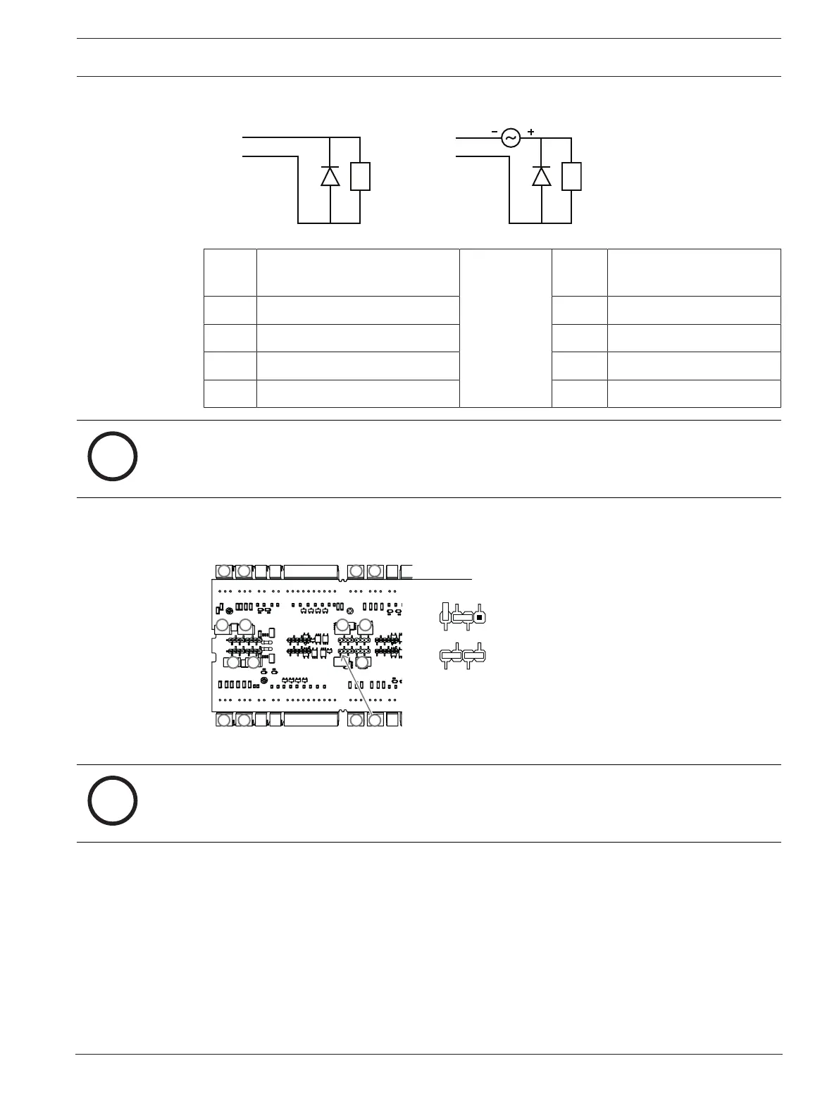
dry mode:
output output
AMC AMC
wet mode:
1
2
1
2
3
5
4
3
4
Figure4.19: Recovery diode schematic
1 normally open/normally closed 1 normally open/normally
closed
2 common 2 common
3 load 3 load
4 recovery diode 4 recovery diode
5 voltage source
Notice!
Risk of damage to equipment
Do not connect externally powered devices in wet mode. This can damage the AMC2.
Each relay output has a separate jumper setting on the underside of the circuit board to select
dry (D D1) or wet (D D2) mode.
D 1:
Auslieferungszustand
D 2:
1
2
5
6
7
8
2
34
34
78 56
Figure4.20: Location of the relay output jumpers (bottom side)
Notice!
The positions of the jumpers 1 and 2 are interchanged related to the corresponding
interfaces.