48 en | Appendices Access Modular Controller 2
2021-04 | V04 | IM
Installation manual
Bosch Security Systems B.V.
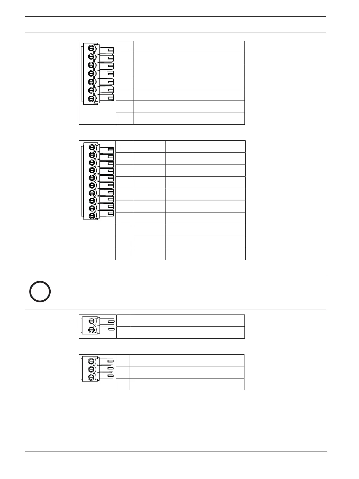
1 Power supply, DC positive (10V - 30V)
2 Shield
3 Power supply (0V)
4 UPS (power good signal) - AC
5 UPS (power good signal) - Battery
6 UPS (power good signal) - DC
7 UPS (power good signal) - Common
Tab.11.6: Power supply
1 red Reader Supply (12V)
2 black Reader Supply (0V)
3 green Data 0
4 white Data 1
5 drain Shield
6 orange green LED
7 brown red LED
8 yellow Beeper
9 blue Hold
10 violet Card Present
Tab.11.7: Wiegand interface AMC
Notice!
For reader settings refer to the respective reader manual.
1 Analog Input, in
2 Analog Input, out
Tab.11.8: Analog input
1 Relay Output, normally open
2 Relay Output, common
3 Relay Output, normally closed
Tab.11.9: Relay output