List of Figures Access Controller AMC-4W
52 Installation Guide Bosch Security Systems | V.3.1/2006-09
8. List of Figures
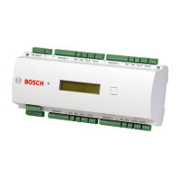
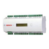
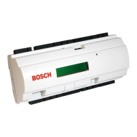
Figure 1: The Access Controller AMC-4W...................................................... 11
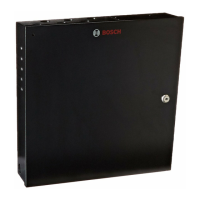
Figure 2: The AMC-4W in a four door safety lock .......................................... 12
Figure 3: Upper circuit board with display (top side)....................................... 13
Figure 4: Lower circuit board (bottom side)..................................................... 15
Figure 5: Lower circuit board connections (bottom side)................................. 16
Figure 6: System overview ............................................................................... 17
Figure 7: Mounting the AMC-4W on a mounting rail...................................... 21
Figure 8: Demounting the AMC-4W from a mounting rail.............................. 21
Figure 9: Opening the AMC-4W case .............................................................. 22
Figure 10: Location of ground jumpers RS485 host interface.......................... 23
Figure 11: Location of ground jumpers bottom side circuit board ................... 24
Figure 12: Location of the power supply connector ......................................... 25
Figure 13: Configuration of an RS485 host system.......................................... 27
Figure 14: Location of the RS485 host interface .............................................. 28
Figure 15: Connection scheme of an RS485 two wire connection ................... 28
Figure 16: Settings for RS485 two wire connection ......................................... 29
Figure 17: Connection scheme of an RS485 four wire connection................... 29
Figure 18: Settings for RS485 four wire connection ........................................ 30
Figure 19: Location of the RS485 address selector .......................................... 30
Figure 20: Location of the RS232 serial interface ............................................ 32
Figure 21: Location of the Ethernet interface ................................................... 33
Figure 22: Location of the RS485 extension module bus................................. 34
Figure 23: Location of the Wiegand interfaces for external devices ................ 35
Figure 24: Wet mode and dry mode of the AMC-4W relay outputs................. 36
Figure 25: Location of the relay output connectors .......................................... 37
Figure 26: Location of relay output jumpers (bottom side) .............................. 37
Figure 27: Operating modes of a lock using the analog input device ............... 38
Figure 28: Location of the analog input connectors ......................................... 40
 Loading...

