14/176 Introduction
Bosch Rexroth AG, MIT: ID 40, 3 842 530 344/2014-05
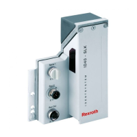
The cover of the HF head lights up once data transmission with an MDT has initiated.
The light deactivates once the control system completes the data transmission with
the MDT.
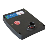
The LED on the MDT lights up once it is in the HF field. The color of the LED
indicates various operating states of the MDT.
Fig. 3:
LED
HF head cover
Data transmission between SLK and MDT
2.2.1 SLK operating states
The SLK has multiple operating states, known as link states. The actual link state can
be changed by a fieldbus command from the user program as well as by the ID 40
system itself.
The actual link state can be determined by the control system at any time using the
fieldbus (for coding, see Chapter 5.3.1 “Actual link state"). An MDT entering the
HF field, for example, is signaled by a change in the actual link state. The SLK also
shows the actual link state on the status display.
The operating states of the SLK are described below. Appendix 16.1 “ID 40 system
link model” contains a detailed overview of the link state.
PROOF COPY 1 | 20.05.2014 | FOR INTERNAL USE ONLY
 Loading...