3/176
3 842 530 344/2014-05, MIT: ID 40, Bosch Rexroth AG
Inhalt
1 About this manual 9
1.1 Scope of Application 9
1.2 Layout of this manual 9
1.3 Display 10
1.3.1 Numbers 10
1.3.2 Operating states 10
1.3.3 Information 10
1.4 Safety instructions 11
1.5 New in the 4.x versions of the ID 40/SLK software 11
2 Introduction 12
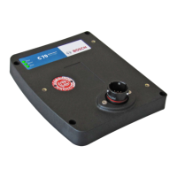
2.1 ID 40/MDT mobile data tag 12
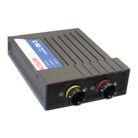
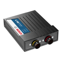
2.2 ID 40/SLK read/write head 13
2.2.1 SLK operating states 14
2.2.2 Status display 18
2.3 Data transmission between SLK and MDT 20
2.3.1 Position of MDT and SLK during data transmission 20
2.3.2 Static and dynamic data transmission 21
2.3.3 Direct and parameterized data transmission 22
2.3.4 Securing data transmission 22
3 Installing MDT and SLK 23
3.1 Mounting the MDT on the workpiece pallet 23
3.2 Mounting the SLK on transfer section profiles 23
3.3 Antenna orientation 24
3.4 SLK electrical connection 25
3.4.1 Supply voltage 25
3.4.2 Connecting the fieldbus 26
3.4.3 Serial interface 27
3.4.4 Turning on the SLK 28
4 MDT memory structure 29
4.1 ID 40/MDT storage 29
4.2 Organization of MDT memory 30
4.2.1 MDT user data area 31
4.2.2 MDT system data area 31
4.2.3 MDT register area 32
5 SLK memory structure 34
5.1 Map of MDT user data area 35
5.2 Map of MDT register area 35
5.2.1 Map of MDT status register 35
5.2.2 Map of MDT pointer registers 35
5.2.3 Map of MDT ID code 35
5.2.4 MDT counter 35
5.2.5 MDT formatting 35
5.2.6 Map of MDT software version 37
5.3 SLK register area 37
5.3.1 Actual link state 37
5.3.2 Commanded link state 38
PROOF COPY 1 | 20.05.2014 | FOR INTERNAL USE ONLY
ENGLISH
 Loading...