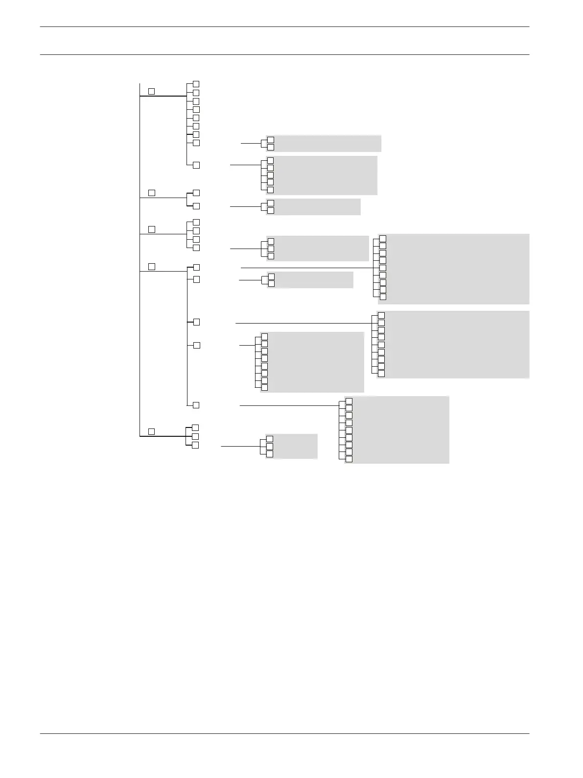
Zone
Zone config
Installer
Passcode
Zone allocate
Zone name
Day alarm zone
STAY2 zone
EOL resistor
Zone state report
4
1
2
3
4
5
6
7
Siren swing shutdown count1
Report swing shutdown count
2
Telco arming sequence
1
Telco disarming sequence
2
Delay alarm report time
3
Kiss-off wait time
4
Delay siren until transmit over
5
Extend wait for handshake
6
Upload/download enable
7
Callback phone number request
8
Callback phone number
9
Siren run time
1
Siren sound rate
2
Siren sound on RF receiver fail
3
Silent zone tamper alarm1
Unseal RF zone that failed monitor
2
Bosch Smart Lockout enable
3
Zone pulse count handover enable
4
Handover delay in order
5
Area
5
Codepad area
Area option
1
2
Output
6
STAY mode arm/disarm report enable1
Arm/disarm report only if alarmed2
First disarm/last arm report3
Arm/disarm report option
4
Codepad report option
5
Test report time and interval
6
Test report only when armed
7
Test report on siren reset
8
Test report option
9
First phone number1
Second phone number2
Transmit format
3
Subscriber ID number
4
IP + Port / Email
Conettix ACK wait time
Conettix heart beat time
Conettix anti-replay enable
5
CSVIP user name and password
6
Ring count1
Report function enable
2
Exit A-Link connection on alarm
3
System status report option
4
Use bell-103 for FSK format5
DTMF dial pulse to 1 digit/sec
6
Set up domestic dialing format
DTMF timing compensation [111]
7
Swing shutdown
8
Zone option
9
Arm/disarm all areas once1
Reset siren from any area2
Onboard output
Codepad output
Extend output
Siren config
1
2
3
4
Comm
7
Receiver config
Network config
Report config
Comm option 1
Comm option 2
1
2
3
4
5
Network module1
A-Link/RSC password
2
Parameter
8
Address program
Address auto step
Adapter
1
2
3
Test adapter
1
Read adapter
2
Write adapter
3
[267]
[502]
[2536]
[265]
[381]
[266]
[392]
[379]
[380]
[498.4]
[396.3]
[492.1]
[494.3]
[494.4]
[501.2]
[500.3]
[518]
[436]
[460]
[646]
[177.4]
[0, 40, 1417, 1457]
[16, 56, 1433, 1473]
[33, 73, 1450, 1490]
[34, 74, 1451, 1491]
[1000, 1200, 2060, 2260]
[1100, 1300, 2160, 2360]
[1401, 1405, 1409, 1413]
[1403, 1407, 1411, 1415]
[1400]
[479]
[480]
[396.1]
[81,82]
[83]
[175]
[177.1]
[180.3]
[427]
[178.2]
[178.1]
[500.1]
[403]
[411]
[428, 434]
[496.1]
[496.2]
[435]
[179.1]
[*]
[474]
[490]
[178.3]
[178.4]
[180.1]
[180.2]
[159]
[113]
[143]
8
7
8
9
* Refer to Command 965 - Set up Domestic Dialing Format, page 27.
WE800EV2 receiver
The WE800EV2 is designed to provide a convenient ON/OFF control for the Solution
2000/3000 series control panel. Provision is also made for the control of up to two (2)
external devices via on-board relays.
Install the module
1. Remove the small knockout in the Solution 2000/3000 control panel for the antenna and
insert the supplied rubber grommet.
2. Install the WE800EV2 PCB in the control panel with the top of the PCB in the slot
provided at the top of the case and secure with the provided screw at the bottom of the
PCB.
3. Thread the antenna wire through the grommet into the “ANT” terminal.
Wire to the control panel
Connect the 3 pin plug to the jumper labeled WE800 on the control panel. Note that the
connector will only install one way. If the relays are to be used, a wire will need to be
connected from the +12V terminal on the WE800EV2 to a +12 terminal on the control panel.
4.2
18 en | Accessories Control Panel
2017.10 | 03 | F.01U.298.026 Installation Guide Bosch Security Systems, Inc.