1 695 655 779 2010-11-9| Robert Bosch GmbH
�8 | WBE 4140 | Diagnostics en
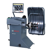
8.2.� Check of the internal pick-up sensor (IN1)
i The sensor is now assembled in the other position.
During appliance check, verify that:
R the stand-by value is half-way on the reading scale;
R by pushing the shaft downwards, the values
increases to end scale;
R by lifting the shaft upwards, the value decreases to
zero.
! The piezo-electric sensors are identical and to
distinguish them, during production, a red pick-up is
assembled on the outside and a black on the inside.
8.� Encoder
i Indicates the function to directly check the step
counter (encoder): the number of spaces varies from
0 to 255.
i The malfunctioning of the apparatus is automatically
detected by the program showing on the display "Err
10" or "Err 11".
¶ By keeping the entry displayed on the board, check
which may be the cause of the fault to be able to
adequately solve the problem (see table below).
Difetto Correzione
The machine
does not reach
255 spaces.
R Check that the disk is not obstructed
by dust.
R Check that the disk is intact.
The machine
does not count
any space.
R Check that the encoder is connected.
R Replace the encoder.
8.4 Engine and power board
i The functioning of the engine is completely managed
by the power board.
¶ If the wheel does not turn listen if, by activating the
cycle, a "click" from the relays is emitted from the
power board..
Difetto Correzione
The wheel does
not turn.
R Check the electric connections.
R Replace the engine or the condensers.
The engine does
not reach the
balancing speed
R Check the tensioning of the
transmission belt.
R Replace the engine or the condensers.
The wheel does
not brake (in
reverse).
R Check, and eventually replace, the
power board.
R Check, and eventually replace, the CPU
board.
8.4.1 Check belt tensioning
To check the tensioning of the transmission belt, use
the tensiometer for optibelt TT mini S belts (nominal
value: 120 ±10 Hz).
8.5 Potentiometers
i The potentiometer used is of multiturn type, where
the shaft must fulfil more than one turn to go from
one end of the run to the other.
¶ To check the correct functioning of the potentiome-
ter, turn the head and check that, during the entire
run, the value is not blocked.
! It is necessary to check the values of the
potentiometers when, during entering of the
measurements, the machine displays the
unacceptable values and, even after calibration of
the callipers, the problem is not solved.
8.5.1 Diagnosis distance potentiometer(IN2)
Difetto Correzione
The value remains blocked
at scale end or between 0
and 40.
R Check that the cable is
correctly connected.
R Check that the steel cable is
in its seat and is not cut.
R Replace the connection
cable.
R Replace the potentiometer.
The value remains blocked
between 100 and 16000.
R Check that the ring nut is
correctly fixed.
R Replace the connection
cable.
R Sostituire il potenziometro.
The values passes from 0
during the run.
Re-position the potentiometer
(see following Instructions).
8.5.2 Diagnosis width potentiometer(IN�)
Difetto Correzione
The value remains blocked
at scale end or between 0
and 40
R Check that the cable is
correctly connected.
R Check that the ring nut is
correctly fixed.
R Replace the connection
cable.
R Replace the potentiometer.