2
CONTENTS
Safety Information.............................................................................................................................3
Warranty .............................................................................................................................................3
Product Description ..................................................................................................................... 4-7
Specifications....................................................................................................................................8
Carton Contents ...............................................................................................................................8
Electrostatic Discharge Sensitive (ESDS) Device Handling .......................................................9
Part List Notes ..................................................................................................................................9
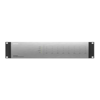
Packaging Part List, ControlSpace
®
ESP-00 II Chassis ..............................................................10
Figure 1. ESP-00 II Chassis Packing View .....................................................................................10
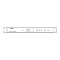
Packaging Part List, ControlSpace CC-16 Controller................................................................. 11
Figure 2. CC-16 Controller Packing View ....................................................................................... 11
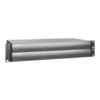
Packaging Part List, ControlSpace CC-64 Controller.................................................................12
Figure 3. CC-64 Controller Packing View .......................................................................................12
Main Part List, ControlSpace ESP-00 II Chassis (see Figure 4) .......................................... 13-14
Figure 4. ControlSpace ESP-00 II Chassis Exploded View.............................................................14
Main Part List, ControlSpace CC-16 Controller ..........................................................................15
Figure 5. ControlSpace CC-16 Controller Exploded View ...............................................................15
Main Part List, ControlSpace CC-64 Controller ..........................................................................16
Figure 6. ControlSpace CC-64 Controller Exploded View ...............................................................16
Electrical Part Lists .................................................................................................................. 17-66
ESP-00 II Motherboard PCB Assembly (Rev. B) .................................................................... 17-24
4x4 Series II PCB Assembly (optional on ESP-00 II) .............................................................. 25-44
Digital Signal Processor (DSP) PCB Assembly ..................................................................... 45-54
General Input/Output (GIO) PCB Assembly ........................................................................... 55-58
Output PCB Assembly ....................................................................................................................59
LED PCB Assembly .........................................................................................................................59
Diodes ..............................................................................................................................................59
CC-64 Control Center............................................................................................................... 60-64
CC-16 Zone Controller ............................................................................................................. 65-66
Disassembly Procedures ......................................................................................................... 67-69
ControlSpace ESP-00 II Chassis ............................................................................................. 67-68
ControlSpace CC-16 Control Center...................................................................................... 68-69
ESP-00 II Indicators and Features........................................................................................... 70-71
Test Procedures ....................................................................................................................... 72-82
Hi-Pot Test.......................................................................................................................................81
Ground Bond Test ..........................................................................................................................82
ADDENDUM A - CSD Configuration Setup ............................................................................. 83-84
ADDENDUM B - Process Summary ...............................................................................................85
ADDENDUM C - Analog I/O Mapping ............................................................................................85
Figure 7. Astec LPT83 Switch Mode Power Supply ........................................................................86
Astec Power Supply +5VDC Voltage Adjustment Procedure......................................................87
Troubleshooting .............................................................................................................................88
Service Manual Revision History .................................................................................................89