87
Astec Power Supply +5VDC Voltage Adjustment Procedure
DC Power Supply +5V Adjustment Procedures
CAUTION: Dangerous voltages are present when the
chassis is powered up and the top cover is off. Use care
when performing the below procedure.
Note: This procedure is to be performed when replacing
the Astec power supply used in the ESP-00 II chassis.
The Astec power supply is set to +5Vdc at the factory.
The ESP-00 II chassis requires +5.2Vdc to operate
properly. Measure the DC voltage level using the follow-
ing procedure. Adjust the 5 volt level if needed.
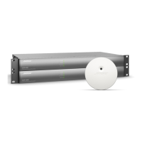
1. Remove the chassis top cover.
Remove the four screws located on the sides of the
power supply that secure the top half of the power
supply cage. Lift off the cage top.
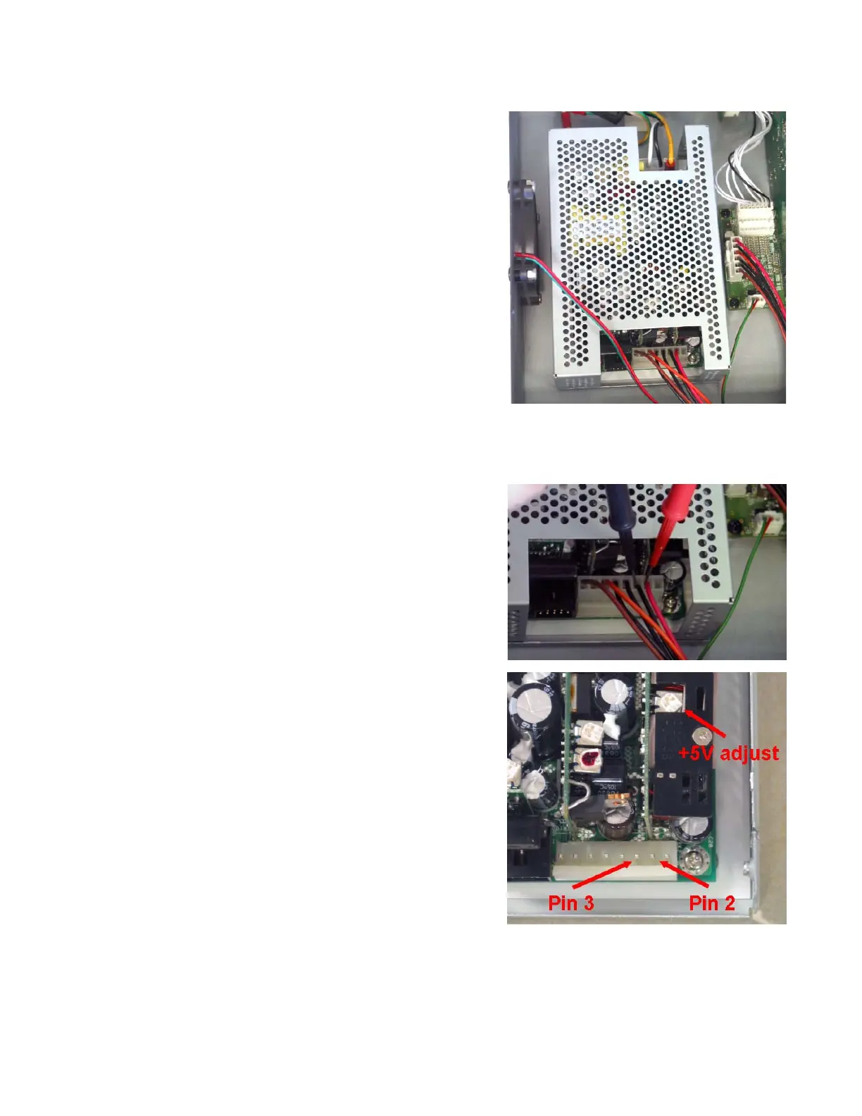
2. With AC mains voltage applied, measure the +5Vdc
level at the DC output connector on the power supply.
Place the positive (+) probe on the red wire at the pin 2
location. Place the negative (-) probe on the black wire
at the pin 3 location.
3. If the DC voltage level reads less than +5.2Vdc, adjust
the +5 Volt potentiometer clockwise until the meter reads
+5.2Vdc.
4. Turn off AC mains to the chassis.
5. Re-assemble the power supply and replace the
chassis top cover.
Astec Power Supply
Note: Production units may not have the
cage that is shown in the photo.