70
3
1
2
1
2
6
7
8
10
5
3 4
9
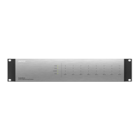
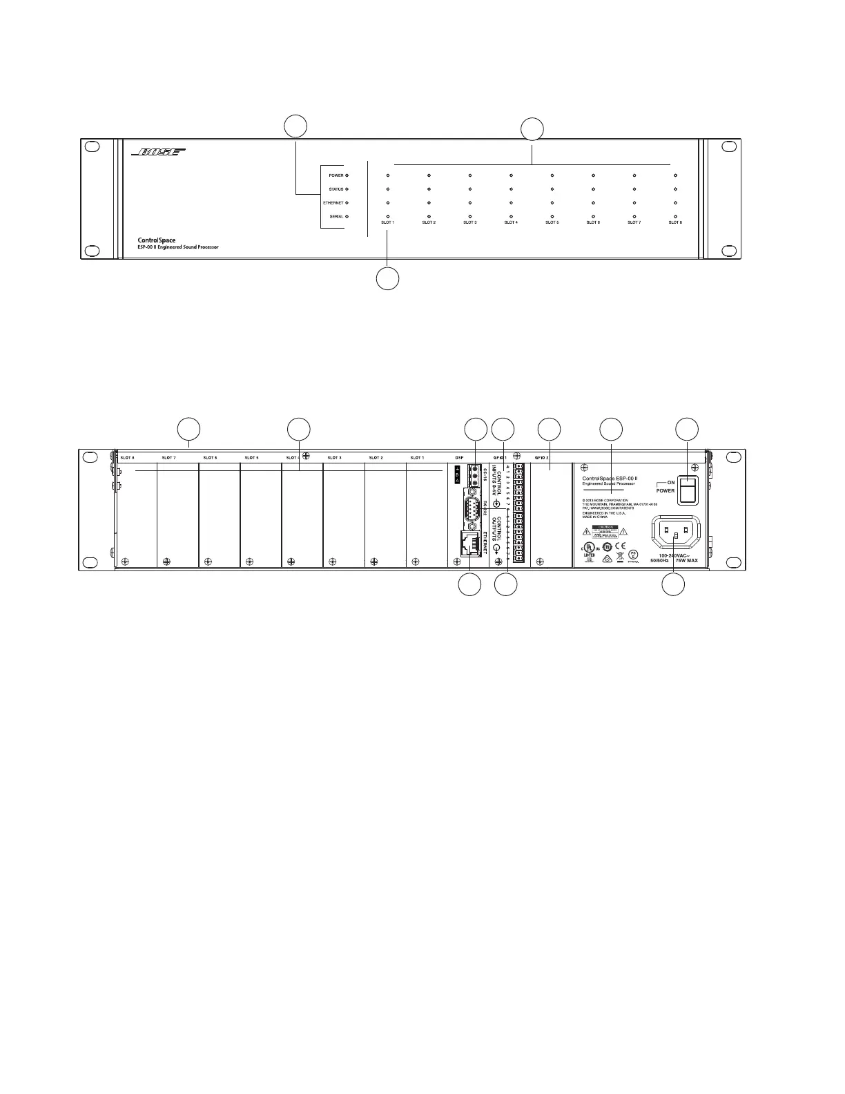
ESP-00 II Indicators and Features
Front Panel
1. LED Indicators: Power, Status, Ethernet and Serial indication.
2. Channel signal indicators: 32 LED windows for channel status from each installed expansion
card.
3. Slot labels: Numbered expansion card location with corresponding signal indicators.
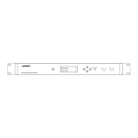
Rear Panel
1. Top panel: With the removal of eight screws, lid removes to allow installation of expansion
cards.
2. Card slot panels: Removable panels, houses up to eight expansion cards.
3. CC-16 connector: Allows Bose CC-16 zone controller connections.
4. GPIO slot 1: Pre-loaded GPIO card which provides eight general purpose control inputs and
eight general-purpose control outputs.
5. GPIO slot 2: For optional 2nd GPIO card.
6. Chassis serial number: Location for unit serial number.
7. POWER switch: AC power switch.
8. AC mains receptacle: Power cord connection (IEC 60320-C-14 Inlet).
9. RS-232: 5-wire, RS-232-C (DTE) serial data interface connection.
10. Ethernet connector: RJ-45 jack for network connectivity.