75
TEST PROCEDURES
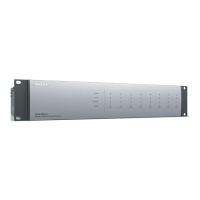
1.2 Refer to Figure A at right. It illustrates the cabling connections to the ESP-00 II and the Audio
Precision ATS-2 (AP). This is the standard test gear for performing the test. Other audio signal
generators and analyzers may be used instead.
1.3 Connect the XLR Input and Output cables to the AP using XLR to Phoenix connectors. See
Figure A.
1.4 Connect a CAT5 Ethernet cable
to the DUT Ethernet jack of the DSP
board and to any port of the Ethernet
Switch. See Figure B, orange cable.
1.5 Connect the DB9 Null Modem
Cable to the DUT DB9 connector on
the rear panel of the ESP DUT and to
the USB serial adapter. Connect the
USB serial adaptor to any USB port
of the PC. See Figure B.
1.6 Using a 3-pin Phoenix connector,
connect the CC-16 to the RS-485
port on the rear of the DUT. See
Figure B.
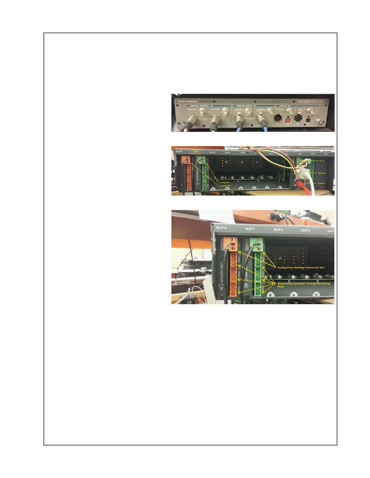
1.7 Connect the AP Analog Output to
the DUT using the XLR Female to
green Phoenix connector cable, and
to the Analog Input CH1 of the DUT.
Connect the XLR Male to Orange
Phoenix Connector cable to the
Analog Input of the AP and to the
Analog Output CH1 of the DUT.
See Figure C.
IMPORTANT NOTE: You MUST
connect a 600 ohm resistor across
the + and - pins on the orange Phoenix connector.
This is to ensure proper output loading in order to get the correct readings during test.
Test Process
2. ControlSpace
®
Designer
TM
(CSD) Settings:
This test process utilizes a .csp configuration file within ControlSpace Designer. To re-create
this file, refer to Addendum A. You can also download this configuration file from the Bose
®
Service web page on the ESP-00 II product page.
2.1 Double click on the ControlSpace Designer.exe Icon located on the desktop (may be in the
taskbar on some PCs). This will launch the ControlSpace Designer program.
Figure A
Figure B
Figure C