84
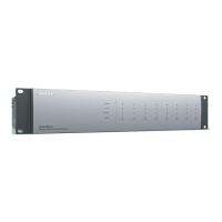
8.5 Add a 4x4 Mic/Line Card as shown in
Figure A4. Right Click the ESP-00 II and
Select Properties. Select the 'Slot 7' Drop-
Down Menu and Select '4X4 Mic/Line'. Close
Properties.
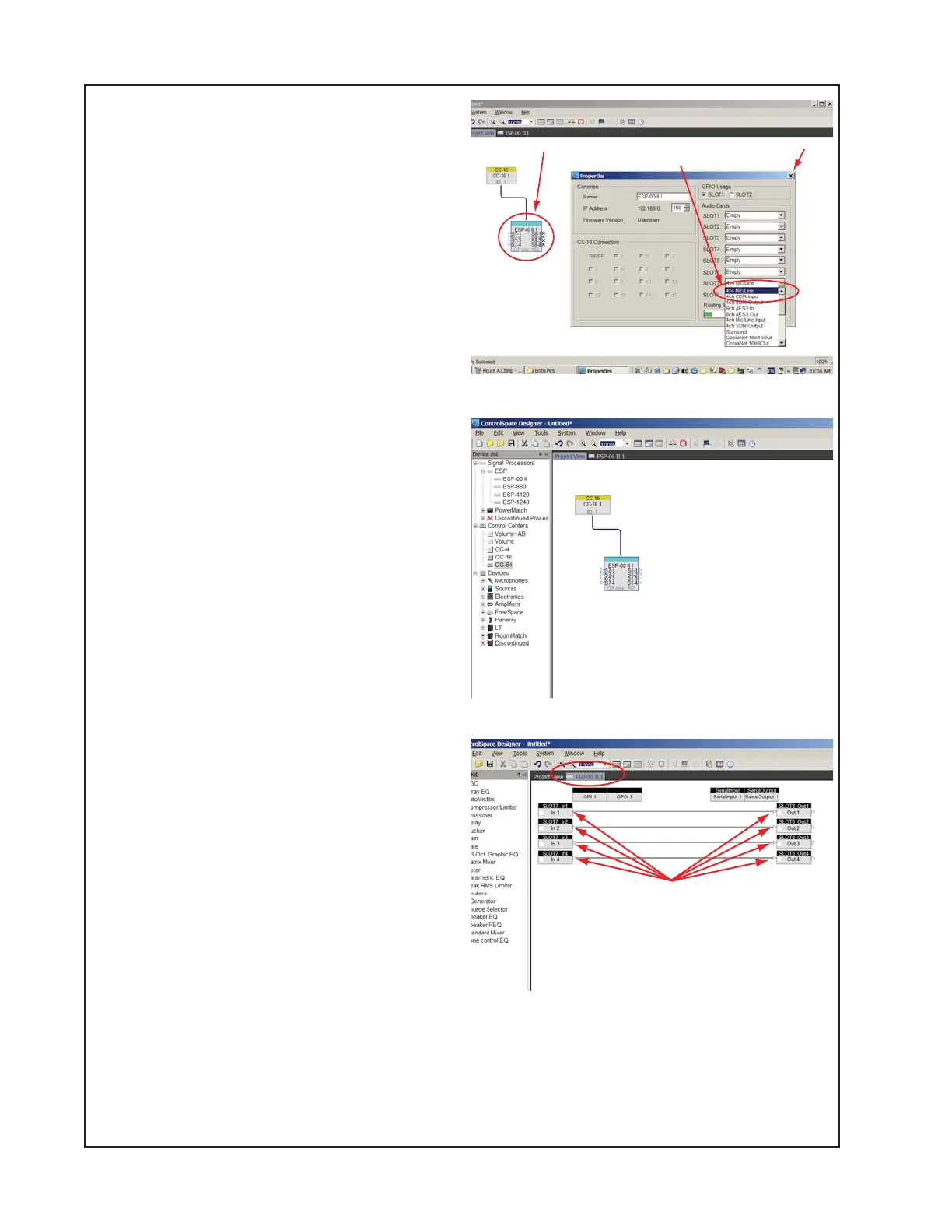
8.6 The 'Project View' tab should look like
Figure A5.
8.7 Select the ESP-00 II tab to view the
internal hardware configuration of the
ESP-00 II.
8.8 Wire the Inputs to Outputs as shown in
Figure A6 by dragging from each input to
each output.
8.9 Save the file by clicking
File>SaveAs>'ESP-00 II DUT Test Config
Basic.csp' and click Save.
Figure A4
Figure A5
Figure A6
ADDENDUM A - CSD Configuration Setup
Right-click and select ‘Properties’
At the Audio Cards Slot 7 drop-down, select ‘4x4 Mic/Line’
Close Properties
This page will be displayed by selecting the ESP-00 II tab
Wire inputs to outputs as shown here