Multi-DM™ User Manual Section 10 - Reference Information
BMC Document Number: DOC-0009 Rev. 5.2 Page 61
Data Latency
The first component of total system performance is the time it takes to transmit a Frame
of data from the PC to the driver, process (decode) that data, and load it into the
digital-analog converters (DACs). This time period is known as the Data Latency time.
The Data Latency time is dependent upon the length of two overlapping operations:
• The time it takes the PC to transmit a single Frame of data to the Driver.
The start of this part of the process is the start of the Data Latency time period.
The length of the transmission time is dependent upon the size of the Frame
and the speed of the PC to Driver connection.
Note that although for some drivers the host PC can send data for individual or
multiple actuators, Data Latency is measured using a full Frame of data.
• The time it takes the Driver processor to decode and write that data to the DACs.
This part of the process begins almost immediately (typically within a few μseconds)
after the Driver starts receiving data, and it typically extends past when the data
transmission ends. The length of the processing and loading operation is dependent
upon the speed of the on-board microprocessor (typically a CPLD or an FPGA)
and the speed of the DACs.
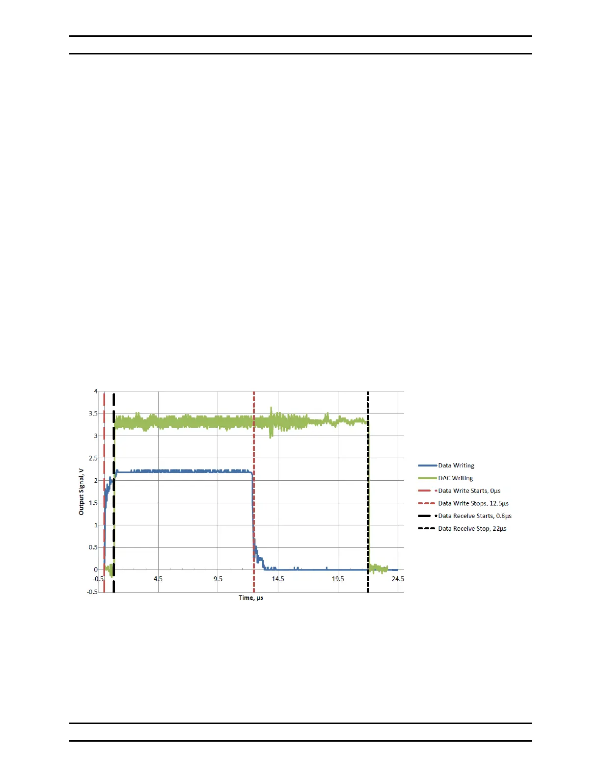
These two components of Data Latency are shown in Figure 12. Note that writing to the
DACs begins right after the data receive starts and continues after the data receive ends.
Figure 12 - Kilo-DM Data Latency
This graph is for a Kilo-DM using a Kilo-class Driver. Other DM sizes are similar.
Boston Micromachines measures and publishes the Data Latency for each
DM and Driver combination.