Do you have a question about the Bowers M1 and is the answer not in the manual?
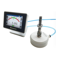
Describes the M1 and M3 display units for dimensional control with air gauges.
Lists the different models (M1, M3) with their references and intended use.
Lists key technical specifications like display type, resolution, connectivity, and dimensions.
Provides physical dimensions and mounting information for the display unit.
Explains connectors, standard cabling, restrictor choice, and by-pass nozzle setup.
Details RS232, Mini-USB, 24VDC, USB Stick, and Footswitch connectors and their functions.
Explains the function of the air gauging pressure variation and the recommended unit.
Describes the air connectors and flexible tubing used with the M1/M3 display.
Divides the M3 graphical interface into two primary sections: configuration and measurement screens.
Defines measurement configurations: Part 1, Part 2, Part 3 class, and control limits.
Configures how measurements are visually presented, including bargraph, needle, and dynamic modes.
Covers device setup, including air gauge calibration (2/3 points) and M-Bus module configuration.
Covers general device configuration settings like communication, language, and footswitch options.
Details how to secure the device settings using a password and lock specific functions.
Explains how to access and use the main measuring screen for taking readings.
Describes the functions of the lateral buttons on the measuring screen (Zero, Clear, Preset, Part).
Lists specific RS232 commands for various configuration windows, including general command rules.
Explains the standard data export format and file naming convention for USB keys.
Details advanced data export methods using QR codes for manufacturing order numbers.
Explains how to use QR codes to execute device calibration commands.
Describes advanced configuration techniques using QR codes, including reset commands.
Provides a practical example of configuring the unit with QR codes for paired measurements.
Details the MB-IO module for handling digital input and output signals.
Describes the MB-RL module used for retrofitting older display units with relay functionality.
Details identifying and configuring the MB-TP temperature module.
Explains setting up temperature modes like Alarm and Compensation.
| Brand | Bowers |
|---|---|
| Model | M1 |
| Category | Industrial Monitor |
| Language | English |