42
Flight control system user manual Agriculture
©2024 Boying General Aviation All Rights Reserved
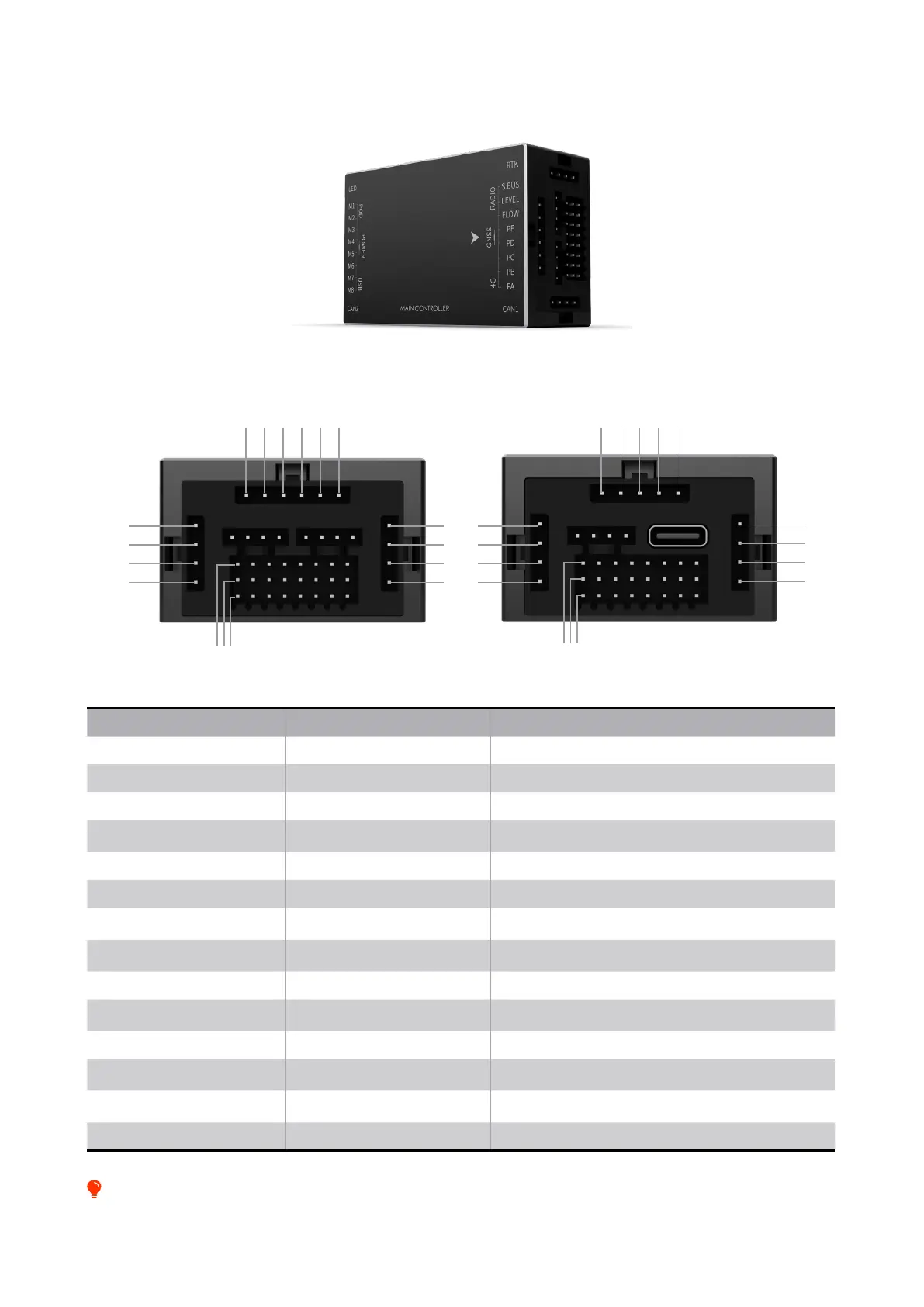
Name Use Remark
RTK RTK module Network version RTK and RTK board
4G 4G interface Provide a network environment for drones
POD Payload interface Imitation ground radar or other payload interface
RADIO Digital radio interface
Keep the radio and antenna as far away from the satellite
navigation module as possible
LED Flight indicator interface
POWER Power interface Supporting power module interface
GNSS GNSS interface
The GNSS antenna should be installed on the surface of the
drone without obstruction
S.BUS S.BUS receiver interface
The interface has 5V power supply, which meets the general
receiving power requirements.
M1-M8 Motor signal output terminal M1~M8 correspond to motors No. 1~8
PA-PE PWM custom interface
PWM output port, corresponding to the auxiliary channel
function
LEVEL Level gauge interface Support 3.5V, 5V, continuous liquid level meter
FLOW Flow meter interface
Can be used for trac monitoring, only one can be selected
with PE port output
CAN1 Smart battery & hub interface
Can be directly connected to the smart battery
communication cable or connected to the hub
CAN2 CAN power communication Can be connected to CAN power
Interface Description
1
1 1
1
1
1
1
1
1
1
12
2 2
2
2
2
2
2
2
2
23
3 3
3
3
3
3
3
3
3
34
4 4
4
4
4
4
4
45 56
Front interface Rear interface
It is prohibited to insert non-Boying wires into the ight control. Wrong wires may cause the ight control to burn out.