40
Flight control system user manual Agriculture
©2024 Boying General Aviation All Rights Reserved
PALADIN-V3
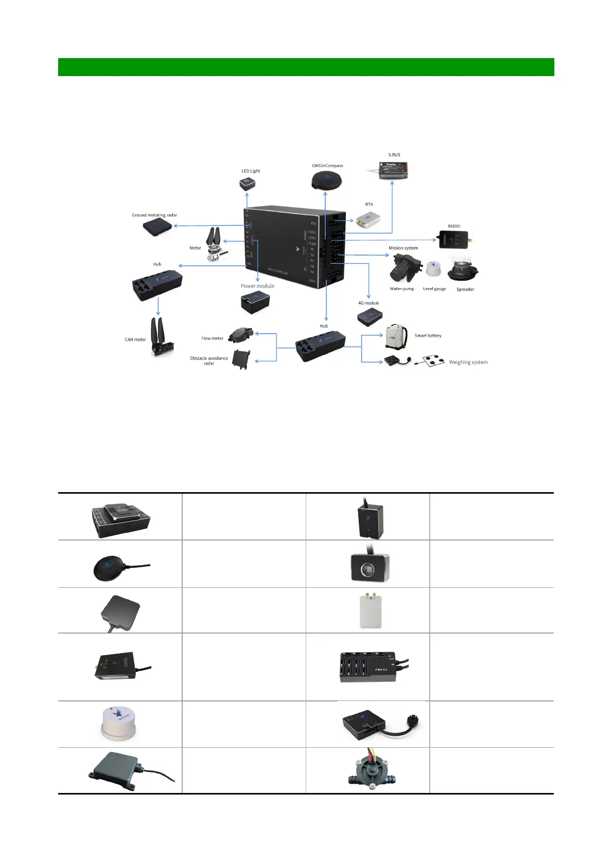
During the installation process of flight control and peripheral equipment, you must pay attention to
the main control direction, and the interface must be installed rmly to prevent virtual connections. The
following gure is a schematic diagram of the connection of ight control peripherals:
System connection
Power module power supply range: The standard power module supports 6S-14S, and the optional high-
voltage power module is suitable for 12S-28S.
Power supply range of the hub: The standard hub V1.0 supports 6S-14S.
Power supply instructions
Main controller Power module
GNSS+Compass
Flight status indicator
light
Obstacle avoidance radar for
UAV high-precision obstacle
avoidance (optional)
Dual antenna RTK, dual
redundant high-precision
orientation and positioning
(optional)
4G module, assists network
RTK positioning and
uploads cloud operation
data (optional)
Hub, used for external CAN
port peripherals such as
obstacle avoidance/ground
imitation radar/intelligent
battery/airspeed meter
(optional)
Liquid level gauge, used
to monitor liquid level and
perform chemical break
protection control (optional)
Weighing system, user
weight detection, combined
with spreader for solid
particle spreading (optional)
Ground-imitating radar,
used for ground-imitating
ight (optional)
Flow meter for detecting
liquid ow (optional)
Conguration list