44
Flight control system user manual Agriculture
©2024 Boying General Aviation All Rights Reserved
Rack setup
PALADIN ight control is suitable for a variety of conventional layout multi-rotor models. In order to meet
user needs, the ground station APP can manually set the rack type. PALADIN provides 11 rack types.
Connect the ight controller and ground station, go to Settings - Rack Settings, select the corresponding
rack type, and conrm to restart the ight controller.
Installation settings
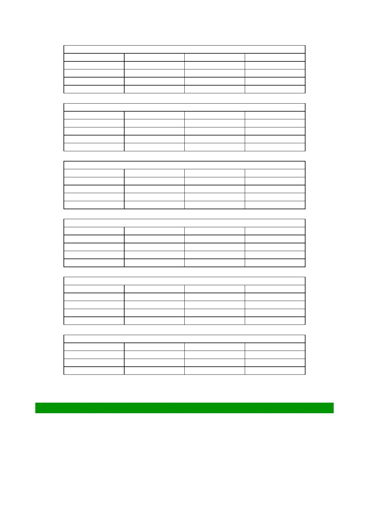
Socket name:RADIO
Pin number Network name Signal direction Signal denition
1 GND OUT Ground wire
2 RXD-1 IN Receive
3 TXD-1 OUT Send
4 5V OUT Power supply 5V
Socket name:POD
Pin number Network name Signal direction Signal denition
1 GND OUT Ground wire
2 RXD-2 IN Receive
3 TXD-2 OUT Send
4 5V OUT Power supply 5V
Socket name:4G
Pin number Network name Signal direction Signal denition
1 GND OUT Ground wire
2 RXD-5 IN Receive
3 TXD-5 OUT Send
4 5V OUT Power supply 5V
Socket name:LED
Pin number Network name Signal direction Signal denition
1 5V OUT Power supply 5V
2 SCL-1 OUT I2C-1 clock
3 SDA-1 IN/OUT I2C-1 data
4 GND OUT Ground wire
Socket name:CAN
Pin number Network name Signal direction Signal denition
1 5V OUT Power supply 5V
2 CAN_H IN/OUT CAN bus high
3 CAN_L IN/OUT CAN bus low
4 GND OUT Ground wire
Socket name:LG
Pin number Network name Signal direction Signal denition
1 CURRENT IN Level signal
2 5V OUT Power supply 5V
3 GND OUT Ground wire