37
Flight control system user manual Agriculture
©2024 Boying General Aviation All Rights Reserved
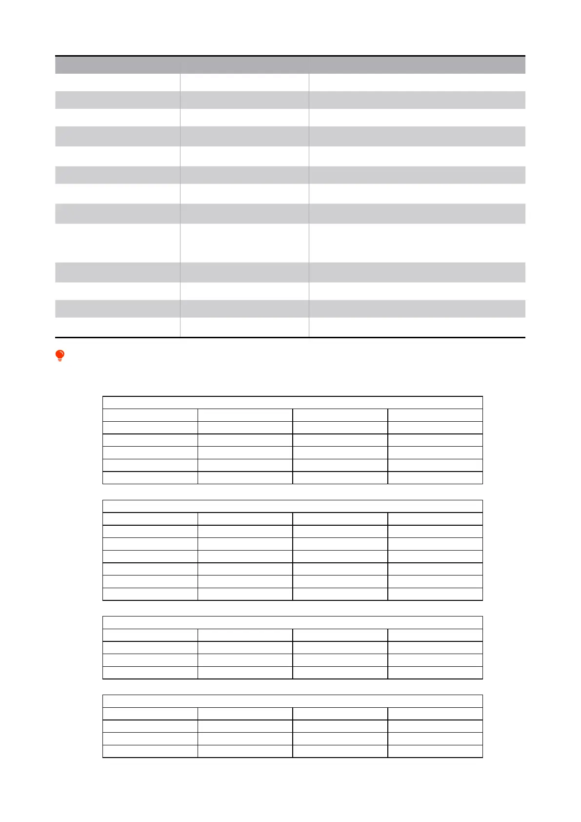
Name Use Remark
RTK RTK module Network version RTK and RTK board
4G 4G interface Provide a network environment for drones
RADAR Imitation ground radar interface Used for imitating ground ight
RADIO Digital radio interface
Keep the radio and antenna as far away from the satellite
navigation module as possible
LED Flight indicator interface
After connecting the external indicator light, the light on the
ight control motherboard will not work.
POWER Power interface Supporting power module interface
GNSS GNSS interface
The GNSS antenna should be installed on the surface of the
drone without obstruction
S.BUS Receiver interface
The interface has 5V power supply, which meets the general
receiving power requirements.
CH1~CH8 Motor signal output terminal
CH1~CH8 correspond to motors No. 1 to No. 8; the signal
line adopts a one-two mode, short wires are connected to
odd-numbered motors, and long wires are connected to
even-numbered motors.
PUMP/NOZ Custom channel interface
Can be connected to PWM signal water pump, centrifugal
nozzle, spreader
FLOW(BUP-POW) Flow meter interface Suitable for PWM input type ow meter
LEVEL Level gauge interface Support 3.5V, 5V, continuous liquid level meter
CAN Smart battery & hub interface
Can be directly connected to the smart battery
communication cable or connected to the hub
Interface denition
Socket name:POWER
Pin number Network name Signal direction Signal denition
1 5V IN power input
2 5V IN power input
3 VOLTAGE IN Voltage monitoring
4 GND IN Ground wire
5 GND IN Ground wire
Socket name:GNSS
Pin number Network name Signal direction Signal denition
1 PWR OUT Power supply 5V
2 TXD-3 OUT Send
3 RXD-3 IN Receive
4 SCL-1 OUT I2C-1 clock
5 SDA-1 IN/OUT I2C-1 data
6 GND OUT Ground wire
Socket name:S.BUS
Pin number Network name Signal direction Signal denition
1 SBUS-PROT IN S.BUS signal
2 5V OUT Power supply 5V
3 GND OUT Ground wire
Socket name:PUMP/NOZ
Pin number Network name Signal direction Signal denition
1 FMU-CH1-OUT OUT PWM control signal
2 FMU-CH2-OUT OUT PWM control signal
3 GND OUT Ground wire
It is prohibited to insert non-Boying wires into the ight control. Wrong wires may cause the ight control to burn out.