38
Flight control system user manual Agriculture
©2024 Boying General Aviation All Rights Reserved
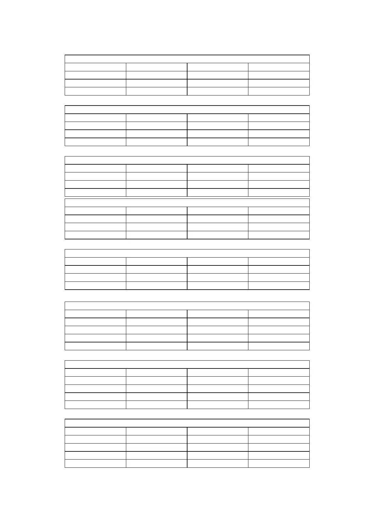
Socket name:FLOW
Pin number Network name Signal direction Signal denition
1 FMU-CH5-IN IN PWM input
2 RX-VDD-5V OUT Power supply 5V
3 GND OUT Ground wire
Socket name:CH7/8
Pin number Network name Signal direction Signal denition
1 IO-CH7-OUT OUT Channel 7
2 IO-CH8-OUT OUT Channel 8
3 GND OUT Ground wire
Socket name:CH5/6
Pin number Network name Signal direction Signal denition
1 IO-CH5-OUT OUT Channel 5
2 IO-CH6-OUT OUT Channel 6
3 GND OUT Ground wire
Socket name:CH3/4
Pin number Network name Signal direction Signal denition
1 IO-CH3-OUT OUT Channel 3
2 IO-CH4-OUT OUT Channel 4
3 GND OUT Ground wire
Socket name:CH1/2
Pin number Network name Signal direction Signal denition
1 IO-CH1-OUT OUT Channel 1
2 IO-CH2-OUT OUT Channel 2
3 GND OUT Ground wire
Socket name:RTK
Pin number Network name Signal direction Signal denition
1 5V OUT Power supply 5V
2 TXD-4 OUT Send
3 RXD-4 IN Receive
4 GND OUT Ground wire
Socket name:RADIO
Pin number Network name Signal direction Signal denition
1 5V OUT Power supply 5V
2 TXD-1 OUT Send
3 RXD-1 IN Receive
4 GND OUT Ground wire
Socket name:RADAR
Pin number Network name Signal direction Signal denition
1 5V OUT Power supply 5V
2 TXD-2 OUT Send
3 RXD-2 IN Receive
4 GND OUT Ground wire