EasyManua.ls Logo

Bray 6A series - User Manual

Bray 6A series
42 pages
Print Icon
To Next Page IconTo Next Page
Loading...
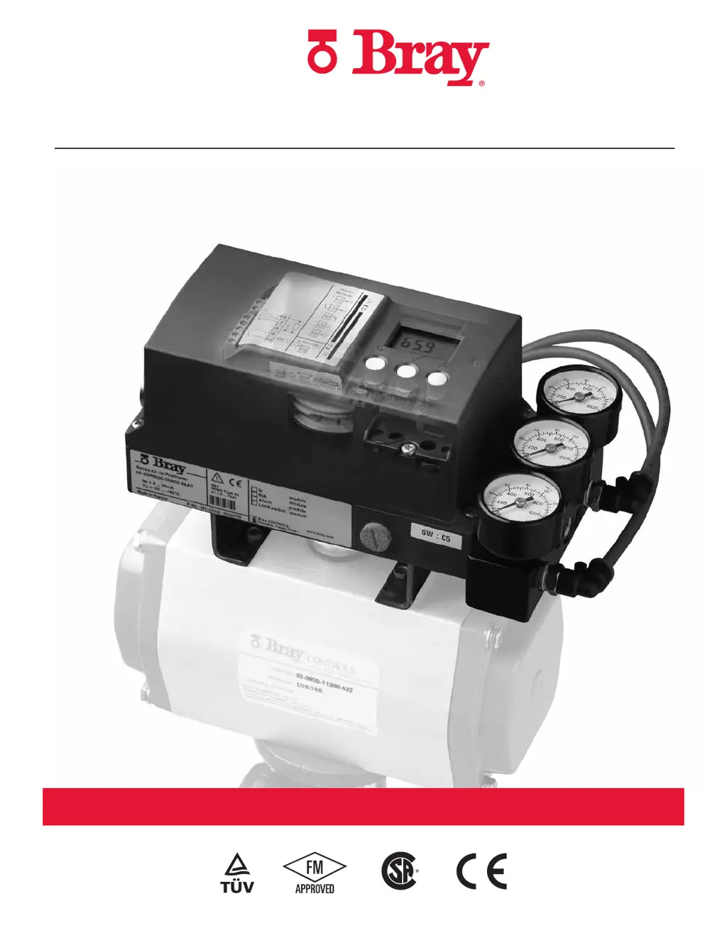
SERIES 6A
ELECTRO-PNEUMATIC POSITIONER
INSTALLATION, OPERATION AND MAINTENANCE MANUAL
The High Performance Company

Other manuals for Bray 6A series

Questions and Answers

  • M
    Megan CampbellSep 9, 2025
    Why does my Bray 6A remain in RUN 1?
    • J
      Jack BuchananSep 9, 2025
      If your Bray Valve Positioner remains in “RUN 1”, it could be because initialization was started from the end position, the maximum response time of 1 minute was not observed, or the network pressure is not connected or is too low. Ensure a waiting time of up to 1 minute, avoid starting initialization from the end position, and provide the necessary network pressure.
  • K
    krystal27Sep 14, 2025
    Why has my Bray Valve Positioners completely failed?
    • S
      scontrerasSep 14, 2025
      If the device function of your Bray Valve Positioners has completely failed, showing no view even on the digital display, it could be due to an inadequate electrical auxiliary power supply. Check the power supply. Also, in cases of very high continuous loads due to vibrations, the screws of the electrical connecting terminals may be loose, or the electrical connecting terminals and/or electronic components may be knocked out. Firmly tighten the screws. For prevention, install the positioner on damping pads.
  • T
    Taylor ZimmermanSep 16, 2025
    What causes zero point displacement in Bray 6A?
    • P
      Paul FrancisSep 16, 2025
      If the zero point on your Bray Valve Positioners displaces sporadically by more than 3%, it is likely due to impact or shock loads causing high accelerations that move the friction clutch, such as from vapor shocks in vapor lines. Correct the causes for these shock loads and then re-initialize the positioner.

Summary

SAFETY INFORMATION

Hazard-free Use Guidelines

General guidelines for safe operation and handling of the device.

Qualified Personnel Definition

Defines who is considered qualified to install and operate the device.

INSTALLATION

Mounting to an Actuator

Provides instructions on how to mount the S6A positioner to an actuator.

FIELD WIRING

General Area Wiring Types

Covers two-wire, three/four-wire, HART, and Profibus connections.

Hazardous Area Wiring

Details wiring for hazardous area installations and intrinsic safety.

CONNECTING PNEUMATIC SUPPLY LINES

RESTRICTORS AND PURGING

CALIBRATION AND COMMISSIONING

Installing a New Unit

Guidance for installing a new positioner unit.

Replacing a Unit

Steps for replacing an existing positioner in a running system.

Operating Modes Overview

Describes the different operating modes: manual, configure, automatic, diagnostics.

Built-in Diagnostics

Details the monitoring functions and diagnostic data available.

Diagnostics Values Overview

Lists and explains various diagnostic values and their meaning.

Parameter Settings

Details the various parameters for configuring the positioner.

FACTORY OR FIELD INSTALLABLE OPTIONS

TROUBLESHOOTING

Fault Message Analysis

Explains fault messages, error codes, and diagnostic parameters.

Remedial Measures

Provides tables for troubleshooting fault profiles and their solutions.

SERVICE AND MAINTENANCE

TECHNICAL DATA

OPTIONAL MODELS

Bray 6A series Specifications

General IconGeneral
BrandBray
Model6A series
CategoryValve Positioners
LanguageEnglish

Related product manuals