SERIES 70 ELECTRIC ACTUATOR
Installation, Operation, and Maintenance Manual
29 of 48
© 2022 BRAY INTERNATIONAL, INC. ALL RIGHTS RESERVED. BRAY.COM
The Information contained herein shall not be copied, transferred, conveyed, or displayed in any manner
that would violate its proprietary nature without the express written permission of Bray International, Inc.
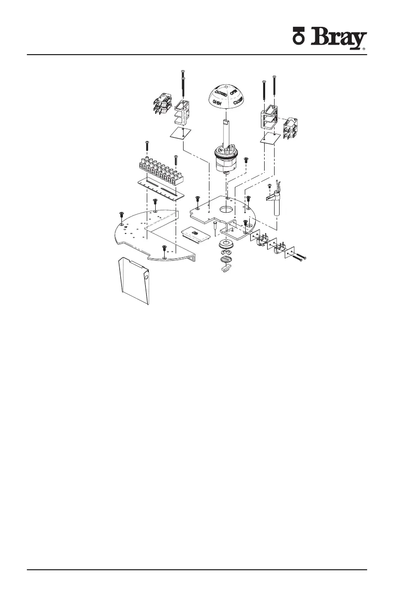
Figure S Actuator Size E E E – switch plate exploded view
9. To remove the gear motor:
a Follow after removing the switch plate
b Disconnect the motor leads which run to the capacitor (VAC motors)
c For Actuator Size E E and E unscrew the mounting screws (two
lower one upper)
d For Actuator Size E E and E unscrew the mounting screws (four
lower one upper)
e For Actuator Size - unscrew the mounting screws (five lower one
upper)
f Remove the motor vertically out of the unit NOTE Do not misplace the
alignment pin(s) mounting screws or lockwashers
10. To replace the gear motor:
a Replace alignment pin (-)
b Place motor into housing and align motor with worm shaft spur gear
c Secure the motor with mounting screws and lockwashers in a “star” pattern
d Manually operate actuator to ensure proper alignment
e Connect motor leads to capacitor (PSC motors only)

 Loading...


