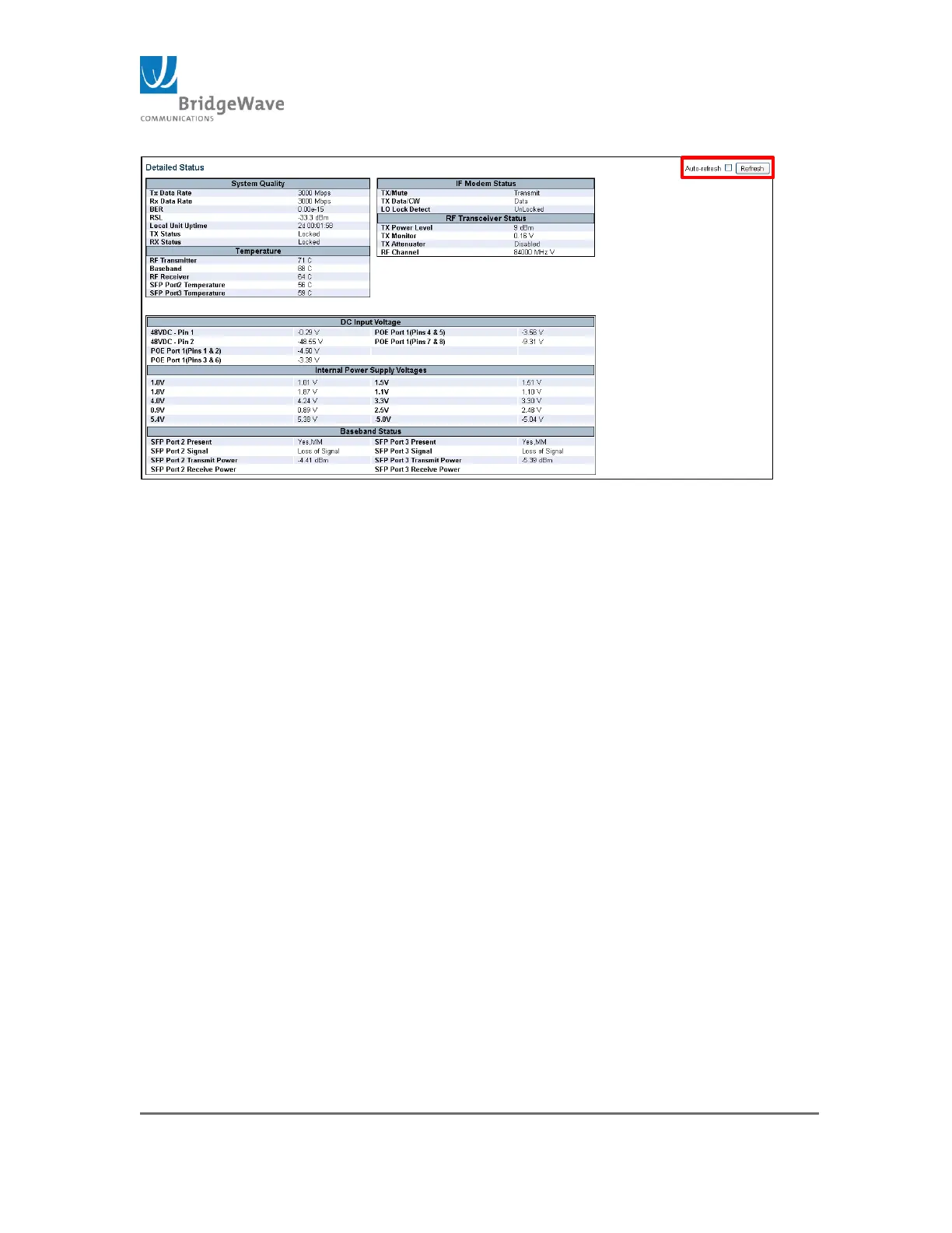
Figure 8: Detailed Status Page
The Detailed Status page is an information page only. The page contains a “Refresh”
button to update the page and it also has an “Auto-refresh” select box to refresh the
page at one second intervals.
The page is divided into seven sections: System Quality, Temperature, IF Modem
Status, RF Transceiver Status, DC Input Voltage, Internal Power Supply Voltages, &
Baseband Status.
System Quality: The System Quality Panel displays the current TX and RX
data rates as well as the current Bit Error Rate (BER) and Receive Signal Level
(RSL). If the link is not yet aligned, or the far end transmitter is disabled, the
RSL will read below -70 dBm. This section also includes the Local Unit Uptime,
the current Tx and Rx status
Temperature: The Temperature section panel displays the RF Transmitter,
baseband board and RF Receiver temperatures as well the SFP temperatures
for both Port 2 and Port 3 (These values are only available when an SFP
module is inside the SFP cage).
IF Modem Status: The IF Modem section displays information related to the
state of the transmitter. The transmitter can be set to “Transmit” “Mute”
and/or “CW”. It also sates whether the Local Oscillator (LO) is locked. If the
LO is Unlocked, this indicates a transmitter failure and the ODU will require
replacement
RF Transceiver Status: The RF Transceiver Status displays the current Tx
power level, the Tx Monitor voltage, the setting of the Tx Attenuator, (Enabled
or Disabled), and the Tx channel setting. By default, the Tx Attenuator will be
“Disable”. The Tx Monitor voltage range is between 0v and 1v. This value
changes the Tx Output power. 0v indicates a possible failure in the
transmitter.