2-6
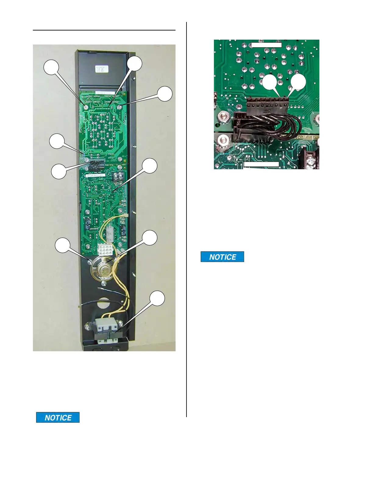
FRONT PANEL ASSEMBLY
DISPLAY BOARD (upper)
The display board (3) displays time and
temperature.
Remove F/C jumper (18)
to display temperature in
Celsius.
3
4
5
6
8
9
7
10
18
DISPLAY BOARD POWER INPUT
To determine if there is power to the upper
Display Board, pull the plug out of the
socket on the Display Board as shown
above.
Turn the unit on and check the voltage
between pins 1 & 2. It should be +5 VDC.
Make sure the red test lead
is on pin 1 and the black
test lead in on pin 2.
If there is 5 volts present then there is
power available to the Display Board.
If the Display Board does not illuminate
when the plug is put back into the socket
then the Display Board is faulty and should
be replaced.
If 5 volts are not present check the power
input to the Control Board (bottom board).
DISPLAY BOARD
CONTROL BOARD
PIN
1
PIN
2
broaster.com Manual #16501 8/06 Rev 10/20