2-7
Replacement:
1. See ACCESS FOR SERVICE.
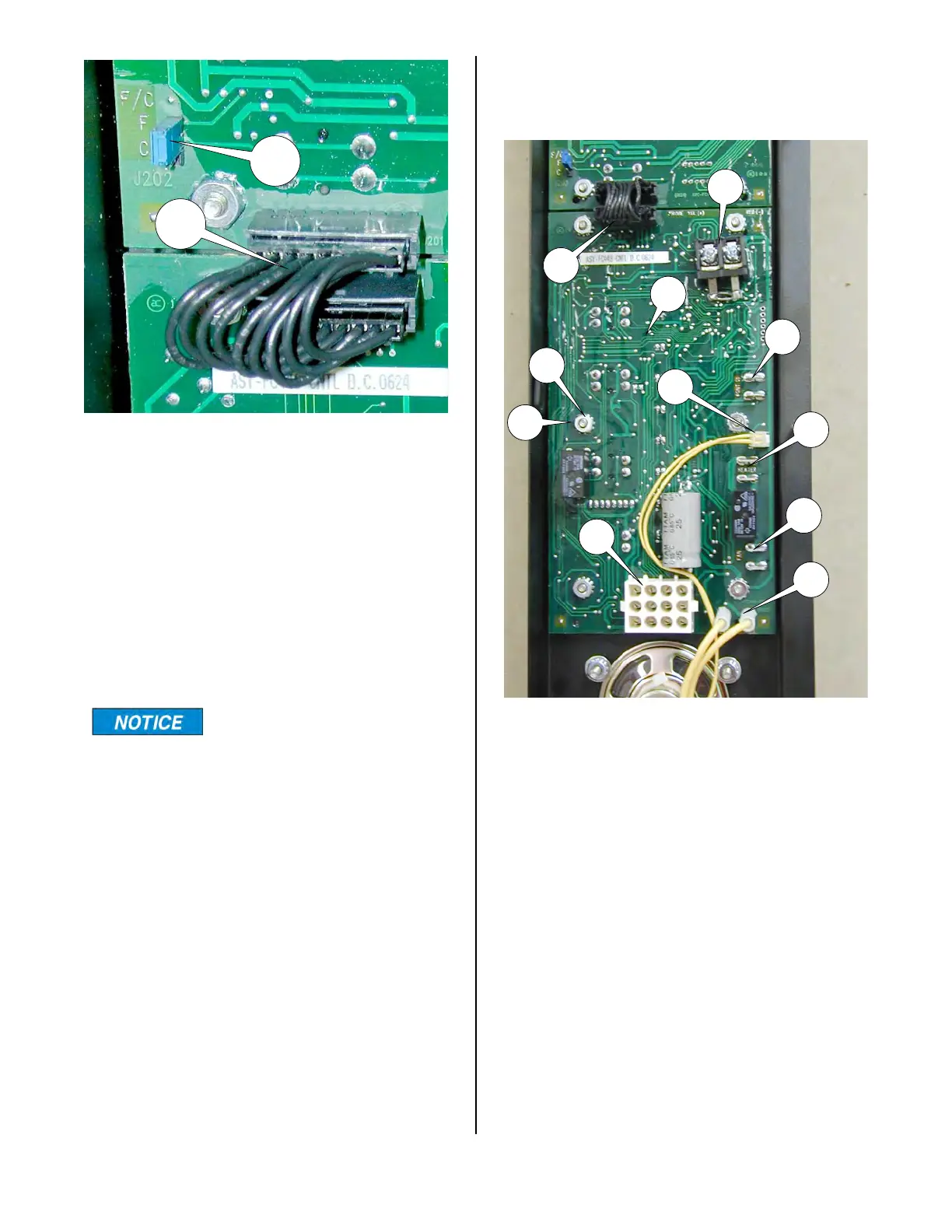
2. Disconnect jumper cable (10) at lower
edge of display board (3).
3. Loosen and remove four hex nuts (4)
and remove display board.
4.Assemble in reverse order.
During reassembly, be
sure the four spacers (5)
are between the main board and the
front panel
CONTROL BOARD (lower)
1. See ACCESS FOR SERVICE.
2. Disconnect jumper cable (10) at upper
edge of control board.
3. Disconnect the red and yellow probe
wires from terminal block (11).
4. Disconnect contactor wires #26 and
#27 from terminals (12) using needle
nose pliers.
5. Disconnect speaker plug (13) from
control board (6).
6. Disconnect heater wires #19 & 20 from
terminals (14) using needle nose pliers.
7. Disconnect fan wires #41 & 42 from
terminals (15) using needle nose pliers.
10
11
12
13
14
15
16
17
4
5
6
18
10
broaster.com Manual #16501 8/06 Rev 10/20