2-8
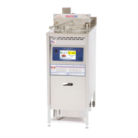
8. Disconnect transformer wires (16) from
control board (6).
9. Disconnect mate-n-lock multi-wire
connector (17) from control board (6).
10. Loosen and remove 6 hex nuts (4) and
remove control board (6).
11. Assemble in reverse order.
During reassembly, be
sure the six spacers (5)
are between the control board (6) and the
front panel.
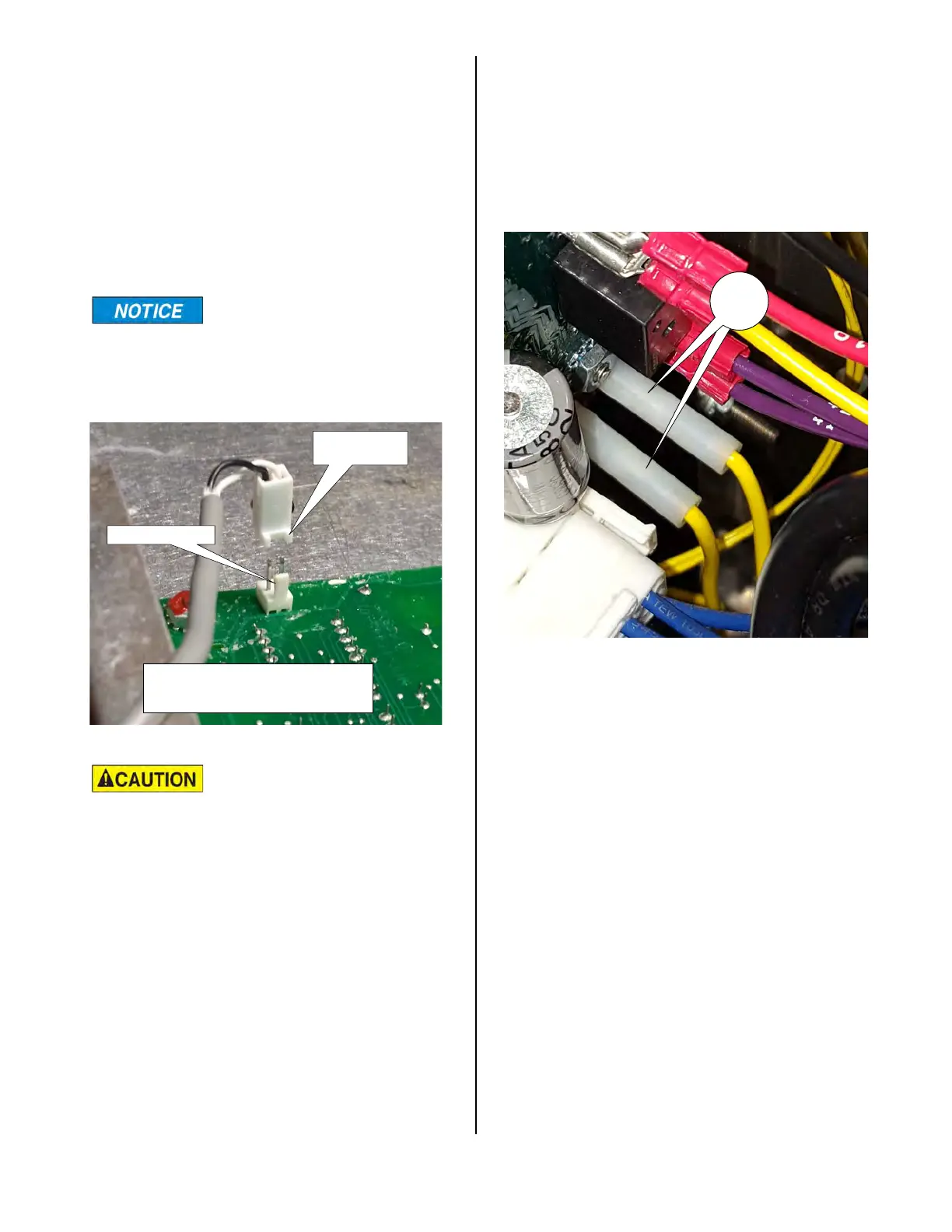
The plastic receptacle
(13) on the speaker wire
and the plastic terminal on the control
board are polarized. Make sure the
receptacle on the speaker wire is
attached to the control board as shown
above to eliminate any problems with
operation of the unit.
RECEPTACLE
LEGS
PLUG POST
THE LEGS ON THE RECEPTACLE
ON THE PLUG.
CONTROL BOARD POWER INPUT
To check the power input to the lower
Control Board, disconnect the trans-
former leads (16) from the lower Con-
trol Board.
Turn the unit on and check the output
voltage from these leads. It should be
24 VAC.
16
broaster.com Manual #16501 8/06 Rev 10/20