4-2
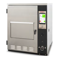
7. Disconnect Temperature Probe wires
from the I/O board terminals (10)
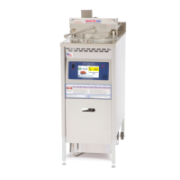
8. Disconnect Hi-Limit Probe wires (R &
Y) form Hi-limit switch (11).
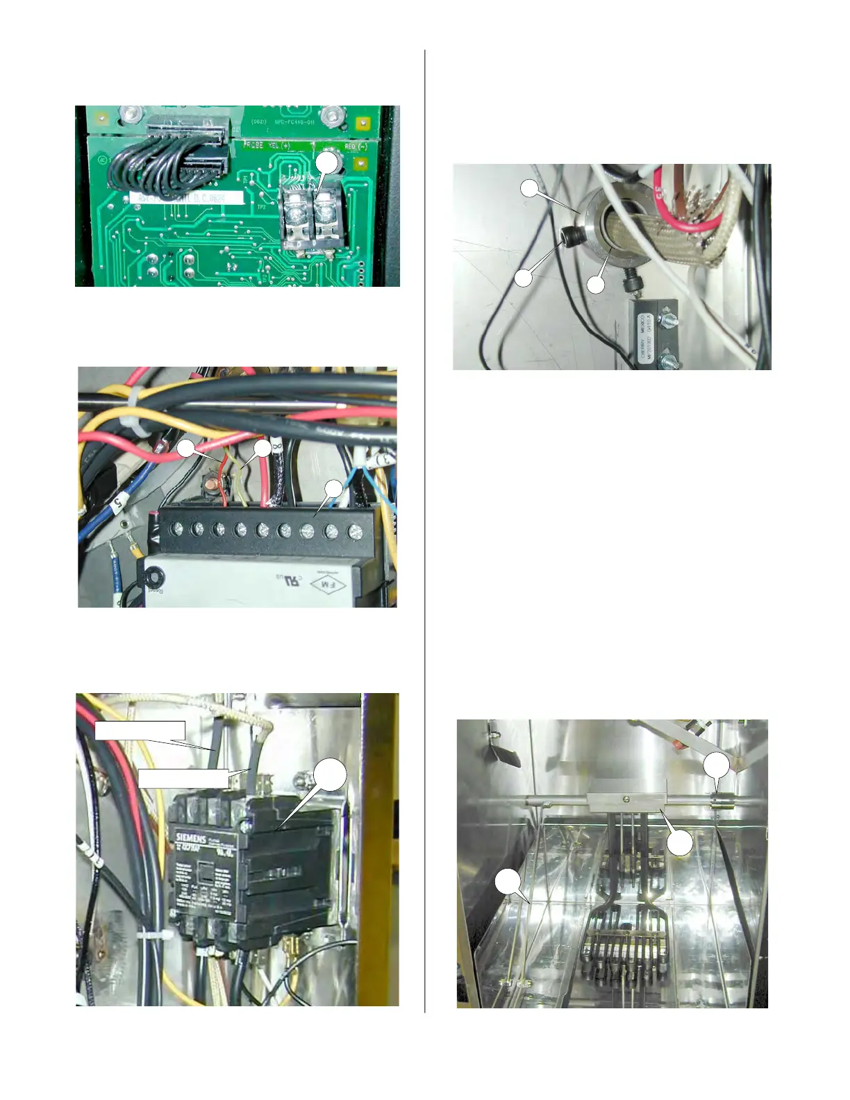
9. Disconnect the Heating Element wires
from the C2 contactor (12).
10
R Y
11
12
Heating Element Wire
Heating Element Wire
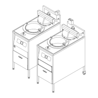
10. With element in up position mark posi-
tion of Set Screw (13) and loosen Set
Screw (13) in the actuating collar (14).
Slide collar off of element shaft (15)
and wires.
11. Lower the element arm (5).
12. Loosen set screw in shaft collar (17)
and slide toward the connector box
(18).
13. Move shaft assembly right to disen-
gage the left end of the shaft assem-
bly.
14. Remove the shaft assembly being
careful not to damage the wire insula-
tion as they pass through the right side
panel.
15 Reassemble in reverse order.
13
14
15
5
17
18
broaster.com Manual #16501 7/06 Rev 2/15