Introduction 8200 Compressor
Installation, Operation and Servicing InstructionsInstallation, Operation, and Service In-
8040353 Brooks Automation
1-4 Revision AA
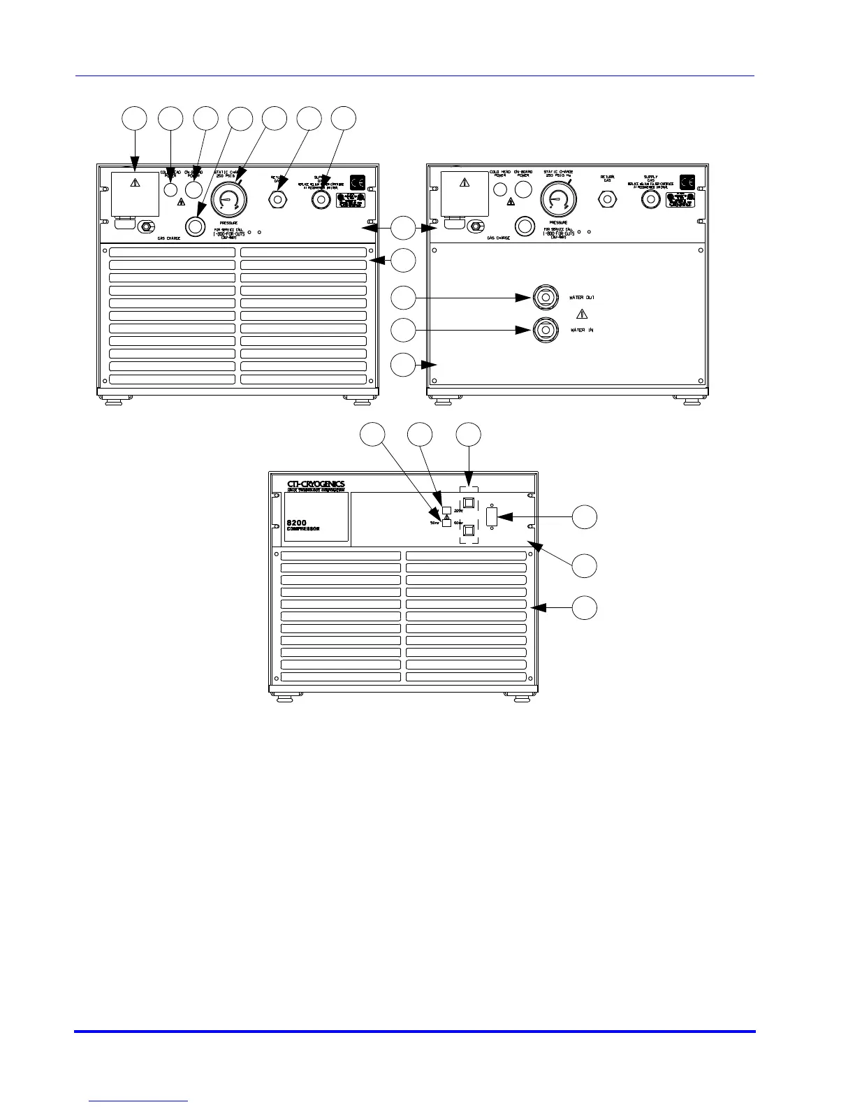
Figure 1-2: Component Locations
16
15
14
13
17
18
10
11
1
2
3
4
5
6
7
8
9
Rear View - Water Cooled
Rear View - Air Cooled
Front View - Air and Water Cooled
1. Compressor Input Power Block
2. Cold Head Power Receptacle
3. On-Board Power Receptacle
4. Helium Gas Fitting and Charge Valve
5. Helium Supply Pressure Gauge
6. Helium Gas Return Connector
12
10. Cooling Water Output
11. Cooling Water Input
12. Rear Plate
13. 50/60 Hz Frequency Selector Switch
14. 208/220 Voltage Range Selector Switch
15. Resettable Circuit Breakers
LEGEND