Do you have a question about the Brother MFC620CN and is the answer not in the manual?
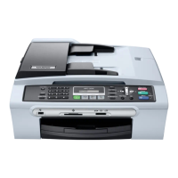
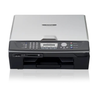
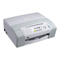
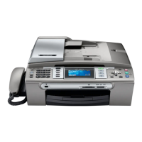
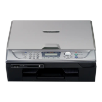
Provides external views and identification of major machine components and their locations.
Details the various keys, buttons, and displays on the machine's control panel.
Lists and illustrates the major internal and external components of the machine.
Lists general specifications like memory, ADF capacity, printer type, power source, and operating environment.
A comprehensive table comparing specifications across different machine models.
Provides a high-level block diagram of the machine's hardware components and their interconnections.
Details the scanning, printing, and paper handling mechanisms, including motors and sensors.
Explains the main electronic components and PCBs that control the machine's functions.
Describes the procedure for transferring unprinted received FAX data to another machine before repair.
Procedures for disassembling and reassembling machine components, including safety and preparation.
Details specific lubrication points and the types of lubricants to be applied during reassembly.
Outlines the necessary requirements, executables, and spare parts needed before performing adjustments.
Details specific adjustments and firmware updates required after replacing the head/carriage or engine units.
Procedures for initializing, customizing, and updating settings after replacing the main PCB.
Explains how to reset the purge counter to zero after replacing the ink absorber box.
Instructions for adjusting the backlight intensity after replacing the control panel PCB.
Describes how to reset the scanner unit type by inputting the CIS type.
Provides detailed procedures for cleaning the maintenance unit, including head caps and wipers.
Explains the embedded and full maintenance programs and how to load them.
Details the procedures for entering the machine's maintenance mode using control panel keys.
Provides a comprehensive list of all available maintenance mode functions and their corresponding reference pages.
Describes how end-users can access specific maintenance functions under service personnel guidance.
Provides in-depth explanations and operating procedures for various maintenance mode functions.
Details equipment and communication error messages displayed on the LCD and their probable causes.
Offers troubleshooting procedures based on problem types, component defects, and common issues encountered.
| Printing Technology | Inkjet |
|---|---|
| Print Resolution | 6000 x 1200 dpi |
| Fax Speed | 33.6 kbps |
| Connectivity | USB, Ethernet |
| Type | Multifunction |
| Functions | Print, Copy, Scan, Fax |
| Fax Resolution | 203 x 98 dpi, 203 x 196 dpi |
| Paper Capacity | 100 sheets |
| Display | LCD |
| Media Types | Plain paper, envelopes, labels |