I: I I I
II
111111111
""
w
AM+w~
N$
;«;
,\1
.54l·<~t
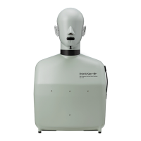
Fig.12.
Rear Panel
of
the 2032
spectrum, coherent or non-coherent
output
power spectrum, liftered spec-
trum,
or any sound intensity
spectrum
can be A-weighted across any frequen-
cy span. Finally, cepstra can be
short
or longpass liftered with selectable
lifter length.
Hard
Copy
from
the
2032
Two possibilities exist for obtaining
a
hard
copy from
the
2032.
The
first is
to
use
the
Graphics Recorder
Type
2313, (Fig.11).
This
is
of
special signif-
icance, since
the
2313 produces fully
annotated
plots
of
the
2032 display,
including
both
graphics
and
alphanu-
merics,
in
less
than
10
seconds
each.
It
also offers
the
possibility
of
further
post
processing
of
results.
The
second
possibility for
hard
copy is
to
use
the
X-Y Recorder
Type
2308. An example
of
such a
hard
copy is shown
in
Fig.13.
Since
the
plot includes automatically
ruled axes, plain
ungraduated
paper
can
be used.
The
2032 also has a video
output.
6
INPUT
CHARACTERISTICS:
Two Identical channels (Channel A &
B)
lnputt: Independent selection
of
3 Inputs on
both
channels
Preamp. Input: VIa standard B & K 7
pJn
"Pre-
amplifier Input• 0
+
28
or
200
V Microphone
Polarization Voltage can
be
selected
Accelerometer Input: Line Drive via
TNC
connector. Coupling: AC 3 dB down at
0,2
Hz
or
3Hz nominal
Direct Input: VIa
~NC
connector. Impedance:
1 M0//100pF.
COUI)IIng:
AC down 3dB at 3Hz
I
Ill
Ill
111111111
•
-
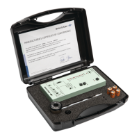
The
Digital Cassette Recorder
Type
7 400 represents a means
of
mass-stor-
age of results from
the
2032.
It
stores
the
results
and
measurement
setup
from
the
2032
in
a form
in
which
they
may be
later
re-entered in
to
the
2032,
used as direct
input
to
a computer, or
plotted
on
the
2313.
At
least 18 com-
plete sets of results can be stored
on
single cassette,
and
more
can
be stored
when abbreviated formats are used.
The
7 400 can also be used
to
store
complete sets of user-defined mea-
surement
and
display setups for
later
re-entry into
the
2032.
Built-in
generator
and
self-test
The
built-in generator
of
the
2032
can supply a sine wave,
random
noise,
pseudo-random noise, or
an
impulse.
The
generator is a zooming generator,
in
that
with a random or pseudo-ran-
dom noise
output,
the
noise
spectrum
is bandlimited
to
match
the
selected
frequency span.
The
frequency
of
the
sine wave is programmable.
The
im-
Specifications
2032
nominal.
DC
with automatic De-offset
compensation
··
Maximum Peak Input Voltage:
28
ranges
+from 15mV
to
100V
In
a 1,5,
2,
3,
4,
6,
8,
10
sequence.
Normal
or
Inverted
Input Autorange: Selects optimum peak In-
put voltage on both channels ·
Maximum Input Voltage: 100V
RMS.
20321s
designed
to
be
operated with Its signal and
chassis
ground at earth potential.
To
ensure
safe operation according
to
IEC
348,
the
volt-
age of the signal ground relative
to
earth
must not
exceed
42
V
RMS
pulse is a signal one sample wide re-
peated
every record,
(that
is once for
every
2048 samples recorded).
The
built-in generator. is for use as a
signal source
in
system measurements,
and
also for self-test of
the
2032.
In
the
latter,
the
2032 is used
to
check its
own functions
and
indicate whether
the
self-test has been passed or failed.
In
the
case of failure, error codes are
given
to
help locate
the
source of
the
fault.
The
2032 performs a self-test
each
time
it
is switched on .
IEC/IEEE
Interface
The
2032 contains as
standard
a
flexible
and
user-friendly IEC 625-1/
IEEE
Std. 488 interface, enabling
it
be
connected to a large
number
of com-
puters, desk-top calculators,
and
other
digital equipment.
The
interface al-
lows Brtiel
& Kjrer
to
offer a state-of-
the-art
modal analysis package, devel-
oped by
Structural
Measurement
Sys-
tems, Inc.,
San
Jose, California as
an
option
to
the
2032.
A feature of
the
2032
IEC!IEEE
in-
terface is
10 special functions keys
mounted
on
2032
front
panel. Each of
these
can
be used
to
generate a service
request over
the
interface, for exam-
ple,· to
start
a computer controlled se-
quence of measurements
in
an
auto-
matic test.
Note
that
it
is possible
to
completely disable
the
2032 front pan-
el controls when
it
under
control over
the
IEC!IEEE
interface.
Fig.13. Example
of
a hard copy obtained
using the
X-
Y Recorder Type 2308
Analog Antlaliaelng Filtere: 2 matched low-
pass
filters with 25,6kHz cut-off
frequen"CY:
Max. ± 0,3 dB ripple In the pa,sband. Provide
at least
75
dB attenu$tlon
of
those Input fre-
quencies
Which
can cause aliasing. Max. gain'
difference: 0,3 dB. Max. phase difference: 3°
up
to
20kHz.
so
up
to
25,8 kHz. The filters can
be
bypassed
Low
Pan
Filten:
2 matched low-pass filters
with
6,4kHz cu,
t-off
frequency. Max. gain
dlf-
·)
terence:
0,1
dB. Max. phase difference: 1 o up
to
6,4 kHz. The filters can
be
bypassed,,
 Loading...