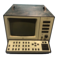
4.2.6. Controls used for Input/Output
Fig.4.9.
DIGITAL
1/0:
r---Digital
1/
0------.
Input
Output
Plot
Stop
Local
IIIII
a a a 1
.
o..:olc,. .•
,..,
...
t$'1)1"•l""•l••••
fypt
2f}~}
·r;;;;;
~
a
11
a a
!l
(it
:'i.'t""·~-
...
.
..
,.
e.
,
..
Controls
used
for
Input/Output
on the 2032
"Input" - causes the 2032
to
input
"Total
Documentation"
and
other
files
over
its
digital
interface
under
manual
control.
The
"Input"
L.E.D.
comes
on,
indicating
that
the 2032 is a listener.
The
2032 Display is
updated,
where
necessary,
after
each file is input,
whereby
the
next
file can be read. On
completion
of
the
digital
input,
DIGITAL
1/0
"Stop"
may
be manually selected,
whereby
the
"Input"
L.E.D.
goes
off,
indicating
that
the 2032 is no
longer
a listener.
Total
Documentation
files
holding
averaged
data
can,
depending
on
the
setting
of
the MEMORY
"Enable"
pushkey, (see Section 4.2.2), be
read
into
the
input
buffer
or
store
buffer. When MEMORY
"Enable"
is
on,
(that
is, L.E.D. on),
read-in
will
take
place
to
the
store
buffer, and
when
it
is off, (L.E.D.
off)
to
the
input
buffer.
For
details
of
the
formats
required
by Total
Documentation
and
other
files
for
digital
input
to
the 2032,
refer
to
the
separate
2032 IEC
Inter-
face Manual.
"Output" - allows
digital
output
of
Total
Documentation
files
con-
sisting
of
both
basic
measured
data, (input
or
stored), and the
MEA-
SUREMENT SETUP, DISPLAY SETUP, CURSOR SETUP, and the
text-
string,
under
manual
control.
The measured
data
output
is:
Single
Spectrum
Averaging
Ch. A
or
8
2048
sample
Time
Function
1024 line
Autospectrum
Single
Spectrum
Averaging
Zero
Pad Ch. A
or
8
1024
sample
Time
Function
1024 line
Autospectrum
41
 Loading...