Measuring Ampifier Type 2525
User Manual Vol.2
2–3
BE1394– 11
Chapter 2 – The IEEE – 488 Interface
Interface Specifications
2.1.3 Interface Addresses
Each device in an IEEE interface bus system has at least one listener and/or talker
address depending on its function. When an interface controller contacts a device
over the interface, it sends a device address which contains the appropriate talker
or listener address. This address is in ASCII (ISO 7-bit) code; bit 8 is not used for
addressing and is ignored.
The 2525 amplifier uses one interface bus address. On delivery, the address is set
to the factory default value 28 (decimal). In order to change the device address you
must manually specify the new address from the Interface Set-up menu. See Volume
1, Chapter 4.
2.1.4 Interface Management Lines
The REN Line
The interface REN or Remote ENable line is used in conjunction with other signals
to select between manual operation via the amplifier front panel controls and re-
mote operation via the interface bus. The REN line is controlled by the device
currently specified as the system controller. Most system controllers set the REN
line to its “true” state immediately on taking control of the bus. For further details
of how this function is implemented in the 2525, see section 2.3 and section 5.2.
The IFC Line
The Interface Clear line resets the interface circuitry to a known operational state.
This IFC line is used by the System Controller to place talkers and listeners in an
un-addressed state.
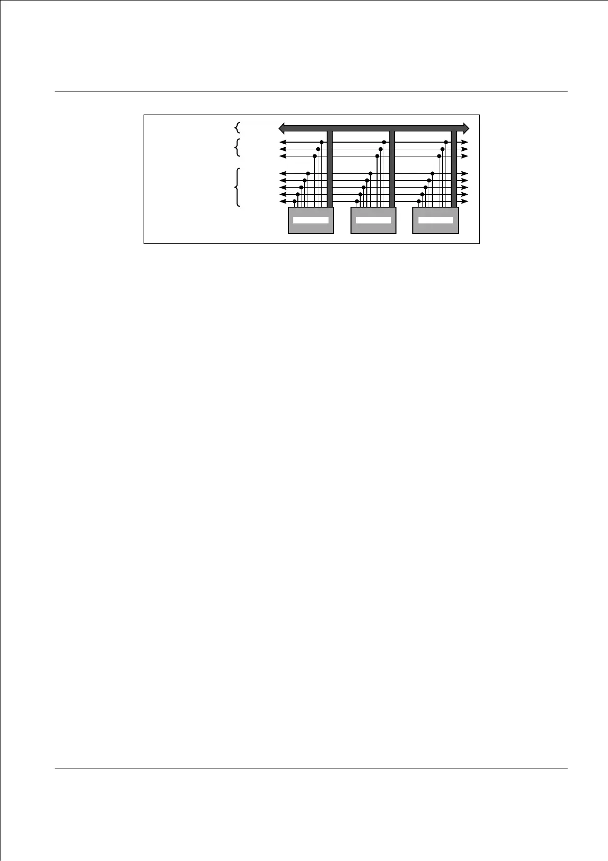
Fig.2.1 Overview of the IEEE bus lines
911870e
DAV
NRFD
NDAC
ATN
REN
IFC
SRQ
EOI
DATA BUS
DATA BYTE TRANSFER
CONTROL BUS
INTERFACE
MANAGEMENT BUS
Data I/O
Instrument Instrument Instrument

 Loading...


